Solenoid, contactor, relay and sensor
Solenoid:
A solenoid is a device comprised of a coil of wire, the housing and a moveable plunger (armature). When an electrical current is introduced, a magnetic field forms around the coil which draws the plunger in. More simply, a solenoid converts electrical energy into mechanical work.
Solenoid, relay and contactor work on the same electo

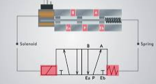
Figure 01: Typical solenoid valve
Solenoids can be used in combination with valves, called solenoid valves. Solenoid valves are common in industrial applications where fluids, such as water and steam, are involved. They turn valves ON and OFF and provide an effective way of switching fluid supply without human involvement.
Common areas of application for solenoid valves include equipment for food and beverage, pharmaceutical, HVAC (heating, ventilation and air conditioning), and utility.
PROGRAM MAIN
VAR
mySolenoid AT%Q*: BOOL;
END_VAR
If we set ON then the valve is opened (if normally closed). If control mySolenoid then we can control the valve (the water and gas can flow and stop the flow).
Relay:
A relay is an electromechanical or solid-state device that serves as a switch to control the flow of electrical current in low to medium-power applications. It consists of a coil, contacts, and an enclosure similar to a contactor. When the coil is energized, it generates a magnetic field that attracts the contacts, either closing or opening the circuit, depending on the relay’s configuration. This allows the flow of current through the connected electrical load. Relays are commonly used in applications with lower current requirements, typically below 15 amperes.
We shall discuss how the relay is controlled by a diagram. Normally we add + power to A1 and – power to A2.
As we see in the following diagram when there is no power then 11 and 12 are connected. When we apply power then 11 and 14 are connected. Here we must note that the controlling circuit and the output circuit are different and those can have different electrical circuit.

Figure 02: Relay and circuit diagram
The following diagram shows how we control the output of the relay. As we see when we have not applied electricity to the control circuit then the circuit for the red LED is complete (default one). So when we have no power at A2 then the red LED burns. When we apply power to A2 by our program then 11 and 14 get connected (thus 12 is disconnected from 11). When the power is applied then the white LED burns.

Figure 03: Controlling relay by using Beckhoff output card (EL2024 for example)
Though we are using here, LED but in real life we can control any device. The output depends on the properties of the relay. The controlled circuit can be for example AC circuit.
See also: Structured Text, Application to control motor control – HEMELIX
PROGRAM MAIN
VAR
myLed AT%Q*: BOOL;
END_VAR
myLed variable can be linked to the EL2024 2nd channel as shown in the above figure. When myLed is false then red LED burns and when myLed is true then white LED burns.
Contactor:
A contactor is an electrically controlled switch used for switching an electrical power circuit for example to provide power to a motor or remove power from a motor. A contactor is typically controlled by a circuit that has a much lower power level than the switched circuit, such as a 24-volt coil electromagnet controlling a 230-volt motor switch.
There is a variety of contractors in the market, we shall describe the functionalities of contactors based on Siemens Sirius type contactors. The following diagram shows how we can make connection/disconnection of supply electricity when we apply control voltage (24V DC) to A1 and A2 then line 1<>2 and 3<>4 get connected, on the other hand, R1<>R2 and R3<>R4 are disconnected.
The control voltage can be applied by the PLC program or by any other programming circuit that can provide a 24V supply. If we want to control the motor (forward and reverse direction) easily we can build it as shown in the following diagram.
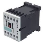
Figure 04: Basic contactor
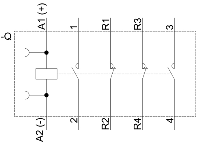
Figure 05: Basic contactor diagram
Reverseing motor direction:
Running motor in one direction is straight forward. We connect supply to motor directly, when we energiged the control circuit then contactor build a path so current can flow and motor can run.
L1 should be connected to T1 (L represents LINE or power and T is for load)
L2 should be connected to T2
For the reverse direction, T2 of the first contactor is connected to T3, and T3 is connected to T2.
Since there is power always in L1, L2 and L3. L2 and L3 will be reverse based on which contactor is active.

Figure 06: Connection diagram, forward and reverse direction
MCB =>MCB Stands for Miniature Circuit Breaker. It automatically switches OFF electrical circuit during any abnormal condition in the electrical network such as overload & short circuit conditions.
MPCB => MPCB full form is Motor Protection Circuit Breaker.
The motor protection circuit breaker (MPCB) protects the motor from faults using a thermal-magnetic circuit breaker. For electric motors, the selection of the MPCB depends upon the motor’s full load current and the maximum short circuit current possible.

Figure 07: Complete diagram for motor control
Sensor:
There are many different types of sensors in the market. Those varies based on the use case of the applications. There are 2 different technologies for the use of sensors in automation technology. 3-wire sensors are very often used in automation. There are 2 different types of inductive proximity switches, optical sensors and capacitive switching sensors: PNP sensors and NPN sensors.
PNP Sensor:
Where the load is connected to the +ve side of the sensor.

Figure 08: Internals of PNP type sensor

Figure 09: Practical example of using PNP type sensor with I/O card
See an actual program at https://www.hemelix.com/scada-hmi/twincat-hmi/hmi_ecdiagnosticscontrol/
PROGRAM MAIN
VAR
myInputCoper AT%I*: BOOL;
END_VAR
myInputCoper is an input type Boolean variable. It can be linked to the actual channel, when the channel data is changed then the framework changes the variable and we can do useful work.
NPN Sensor:
We connect the load to the negative side of the sensor.

Figure 10: Practical example of using NPN type sensor

Figure 11: Practical example of using PNP/NPN sensor with contactor
References:
Continue reading on this page https://www.hemelix.com/automation/structured-text-information-flow-application-to-control-motor/