Basically, a PLC is a digital computer mostly used in the industrial environment. A PLC or Programmable Logic Controller is a type of industrial digital computer which can be used to control a manufacturing process or machine. A PLC, like a computer, has a central processing unit or CPU, memory for the program & data, and a communications interface. Additionally and more importantly, it has an interface to analog and digital inputs and outputs.
PLC Environment
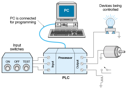
PLC and the development environment, we develop a program in PC and download to PC where the program is executed. PLC reads input (digital inputs and analog inputs) and processes the data and writes to output (digital output or analog output). All these logic are processed in the PLC processor. See how PLC controls the motor in detail.
There are four basic operational steps for every PLC device:
Input Scan: Identifies the status of all input devices that are connected to the PLC.
Program Scan: Implements the user-created program logic.
Output Scan: Either energizes or de-energizes all connected output devices.
Housekeeping: This includes communications with programming terminals and internal diagnostics.
Input Devices
An input device is a piece of computer hardware equipment used to provide data, and control signals to an information processing system.
Some examples of input devices include:
Switches and push buttons
Limit switches
Proximity sensors
Photoelectric Sensors
Vacuum switches
Level switches
Output Devices
An output device is any piece of hardware used to communicate the results of data processing carried out by the PLC, and translate the information into an understandable form. few examples,
Valves
Motor starters
Control relays
Pumps
PLCs can range from small modular devices with tens of inputs and outputs (I/O), in a housing integral with the processor, to large rack-mounted modular devices with a count of thousands of I/O, and which are often networked to other PLC and SCADA systems.
It is needed to automate machines in the industry so that human efforts can be reduced thus minimizing the human errors that might occur in the process. Consider a situation where a human handling a system missed to switch the motor on. Imagine the delay it might cause in the operation to begin. The simple solution to solve this is by automating the motor using PLC. So the basic and most important use of PLC is in the automation of machines.
There are many PLC manufacturers, for example, Siemens, Beckhoff, ABB, Allen Bradley, etc. We shall focus on mainly Beckhoff and Siemens PLC on this site.
There are many ways to program PLC. Ladder diagram (LD) is an easy programming language for beginners, it can be very hard to read and understand. That’s why Structured Text is a better PLC programming language, and you can learn it in this tutorial.
Part 3 of IEC 61131 deals with basic software architecture and programming languages of the control program within PLC. It defines three graphical and two textual programming language standards:
Ladder diagram (LD), graphical
Function block diagram (FBD), graphical
Structured text (ST), textual use similar syntax as PASCAL programming and we shall use ST programming language for both Beckhoff and Siemens PLC.
Instruction list (IL), textual (deprecated in the 3rd edition of the standard)
Sequential function chart (SFC), has elements to organize programs for sequential and parallel control processing, graphical.
Ask questions related to Hemelix sample code and design at Google group https://groups.google.com/g/hemelix