Motor Control Software to Hardware
Information flow from high-level Application to Motor control:
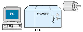
When we press a button on our application then we see we can start a motor or stop the motor. How does the magic happen? There are many ways to achieve this, we shall describe with examples and explanations of how do we achieve this. We need a hardware configuration for this (we have ignored all safety and security related issues in this example for simplicity, in a real project we should not)
BOOL constants are the truth values TRUE (1, 24 volts) and FALSE (0, 0 volts). This can be a starting point for our high-level language. If we set our Boolean variable to HIGH then it means we are going to write to the output device 1 (in most cases it is 24V). See below the explanation of how the message flows from one point to another point.
Version 1.0 Motor Start and Stop
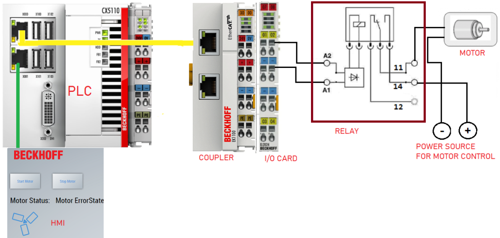
Figure 01: HMI to motor, information flow, HMI to motor (motor start and stop, in real life we use contactor for motor)
As we see in Figure 1, when we don’t have power at A2/A1 then the output of the relays 11 and 14 is not connected. Since 12 is open there will be no effect on the motor. But when we shall apply power to the relay then 12 and 11 are disconnected and 11 and 14 get connected. At this point, the motor starts to rotate as it gets connected to the power source. The most important thing is that the power source is independent of the control circuit (the left side which is 24 DC). The motor power supply can be AC, DC, LOW HIGH voltage (only restriction if the relay allows)
Note: In real life, we use a contactor for controlling a motor, but the principle is the same
PC is where we are running the high-level program (A graphical user interface). There is a read button to read the status of the motor (not used in our example to simplify). There is a write button for writing status 1 (for running the motor) and 0 (for stopping the motor). TwinCAT HMI framework is used to create the HMI which in turn communicates with the coupler and finally communicates with the relay.
HMI (Our application):
Our application is very simple, there are 2 buttons in the graphics.
START button: When we press the START button then it will start the motor. When we press the STOP button the motor will stop
We have only the start and stop feature, there is no direction control or speed control in this version. Here is a link to how to develop TwinCAT HMI at https://www.hemelix.com/scada-hmi/twincat-hmi/
PLC:
We assume that we are using a PLC from Beckhoff. We use the Engineering Tool provided by Beckhoff. The engineering will set up all the necessary programs which are needed to run the motor.
We are running a program in the PLC. The program continuously monitors each variable (this is called a tag or symbol) at some millisecond intervals. We have a variable called bStartMotor. If the variable is modified by our GUI application then it is reflected in the PLC program. PLC Program notices that and writes the value to the output card. If the value is TRUE (1) then it writes 1 and if it is FALSE (0) then it writes 0. Writing 1 means for the output card is that the output card raises the signal to 24 volts. For this purpose, we use the EL2024 output card.
Output card EL2024:
A PLC is always associated with input cards and output cards. Input cards are for reading data and output cards are for writing data. Reading data means the input card senses if there is a presence of 24 volts in the signal pin. If the value of the signal pin is high (24 volts) then the TwinCAT system sets the value of the associated variable value to true (1). The red wire is for 24 volts and the blue one is for 0 volts or ground. Output card starts with the number 2
Electromagnetic coil (Relay):
The output channel of the card is connected to the relay. A relay is an electrically controlled switch used for switching an electrical power circuit. A relay is typically controlled by a circuit that has a much lower power level than the switched circuit, such as a 24-volt coil electromagnet controlling a 230-volt motor switch. In this case, we are running a small DC motor by 6 volts. But our control circuit uses 24 volts.
Whenever we supply 24 volts to the electro-magnetic coils, then it generates magnetic force. In the relay, when we supply 24 volts (by the program, which means when we set TRUE to the variable) then lines 11 and 14 are connected. At this time, current starts to flow via the motor, and the motor starts to rotate. When we remove the power from A2 then 11 and 14 get disconnected and 11 and 12 get connected. 11 and 14 are connected but there is no supply so the motor stops.
Electric motor:
The very cheap (a few euros) electric motor is a low-power DC motor. If we put the power it will start to rotate and if we remove the power it will stop to rotate. If we change the polarity then will start to rotate in the reverse direction. If we change the current flow then it will rotates slowly. In this version, we have only, the start and stop features, reversing and speed control are coming later.
Download version 1.0 (only start and stop)
Version 2.0 Motor Start, Stop and Direction Control
In this version, we shall add direction control of the motor, we shall have the same function as before, we shall change the HMI, PLC program and the hardware configuration to achieve this. Coming soon

Figure 02: Motor reverse and foward direction control (we use multiple relay to achieve this)
Version 3.0 Motor Start, Stop, Direction and Speed Control
In this version, we shall add speed control of the motor, we shall have the same function as before, we shall change the HMI, PLC program and the hardware configuration to achieve this. Coming soon
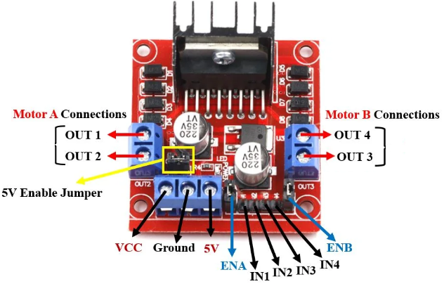
Figure 03: Speed control of DC motor by using L298N motor driver
Next
Download the sample code from the link given above and test it.
See next our article VFD (variable frequency drive) at https://www.hemelix.com/automation/vfd/
Ask questions related to Hemelix sample code and design at Google group https://groups.google.com/g/hemelix