
TwinCAT Software Testing
What is Software Testing
Software testing is the process of checking the quality, functionality, and performance of a software product before deployment to the actual devices. We shall focus on this article while we develop our software when the actual hardware is not available yet. There are many different kinds of testing in software engineering.
In most cases, the PLC software reads, processes, and update the output variables for controlling the devices. The PLC program does some output and then the automation system signals (by input sensors) that it has done the desired work. PLC monitors the input variables for a certain time, if the desired input is not set within that time, PLC signals with an alarm for that device.
As we see in the following diagram, our program continuously reads the inputs and decides what to do, if the program instructs to do an output then it does. The output normally activates the actuators. It can be solenoid valves, it can be a motor contactor. Actuators are devices that perform actions, such as opening valves, moving robots’ arms, or switching lights, based on signals from PLCs.
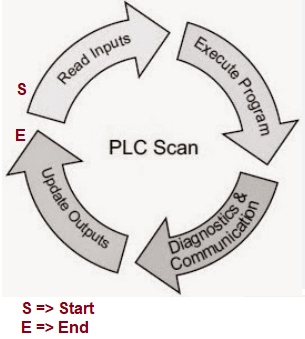
Figure 01: Typical PLC cycle
We can also test the PLC program by creating another task in the PLC program, where we can signal the input to the desired level. Here we are doing similarly but using HMI Software. The test cases can be flexible and visually observable.
Knife Gate Valve (Case Study)
In this tutorial, we shall use a simple knife gate valve. We assume that this one is a pneumatic valve. The valve is opened when a solenoid is active (the output is ON). When the solenoid is ON then compressed air pushes the valve’s blade to the upper direction and the blade goes up. There are two proximity sensors for the valve. When the valve is fully open, the blade is in the upper position, and both proximity sensors are ON. If the lower one is ON and the upper one is OFF then the valve is half open. When the solenoid is OFF then the valve’s spring force pushes the blade to close the valve. When the valve is closed then both proximity sensors are OFF.
The valve is shown in the following diagram.
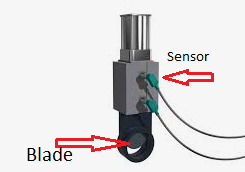
Figure 02: Pneumatic valve, 2 proximity sensors, and a solenoid valve (not shown here)
In the following code snippet, we command the valve to be opened by an action where we put the solenoidOutput variable ON (TRUE)
VAR
upperProximitySensor AT%I*: BOOL;
	lowerProximitySensor AT%I*: BOOL;
solenoidOutput   AT %Q* : BOOL;
	pressureRawValue AT%I*: DINT;
	temperatureRawValue AT%I*: DINT;
	terminalState AT %I* : 			WORD;
END_VAR
Note from the above code that few variables are commented as input, output and analog. By this way, we scan the variables and identify which variables are related to hardware device. For example, when the solenoidOutput is active (ON) then the valve should be in open state and the two proximity sensor should be active (ON) in ideal case. When the solenoid if inactive then the valve should be in closed position and the two proximity sensors should be inactive (OFF)
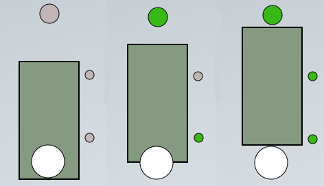
Figure 03: Pneumatic valve closed, partially closed, and fully open (right side of the image) and status of proximity sensors
We shall develop our test system without any physical valves, when our SW is tested then we just activate our program to the PLC then we are done! Following diagram shows possible commands and related results, we can develop similar cases based on our devices and process.
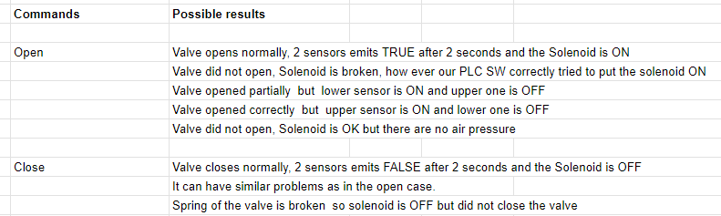
Figure 04: Valve Open and Close command and the possible results of the command
Different devices will have different inputs, outputs and command. These are just an example.
Possible Hardware Setup
We don’t have the hardware yet but we can configure the possible setup in Visual Studio. An embedded PC has a coupler connected to an ethernet port. Two cards EL2008 (Output card) and EL1808 (Input card) are connected to the coupler. The variable solenoid output is linked to 1st channel. The variables upperProximitySensor and lowerProximitySensor are linked to the 1st and 2nd channels of card EL1808. This is drawn as in the following image.

Figure 05: Hardware setup for controlling the valve (simplified version, electrical safety stuff omitted).
With this setup, we activate our tested program, which should start working when the hardware is available. Since we don’t have the hardware yet we shall try to complete the test using our test tool ADSTestDriver.
Valve control Code in ST
In this section, we shall focus on the implementation of valve control in the structured text programming language.
Please download the source code from the download section. This is basically a valve function block that can be used to control the actual device. We have 3 other variables which are not related to the valve itself, those are terminalState of type WORD, pressureRawValue of type DINT, and temperatureRawValue of type DINT. We shall show how we can generate pressure or temperature data while we don’t have actual hardware. The terminal state is another important variable that indicates the communication status with hardware. We can set that status by using our test software.
Testing the valve
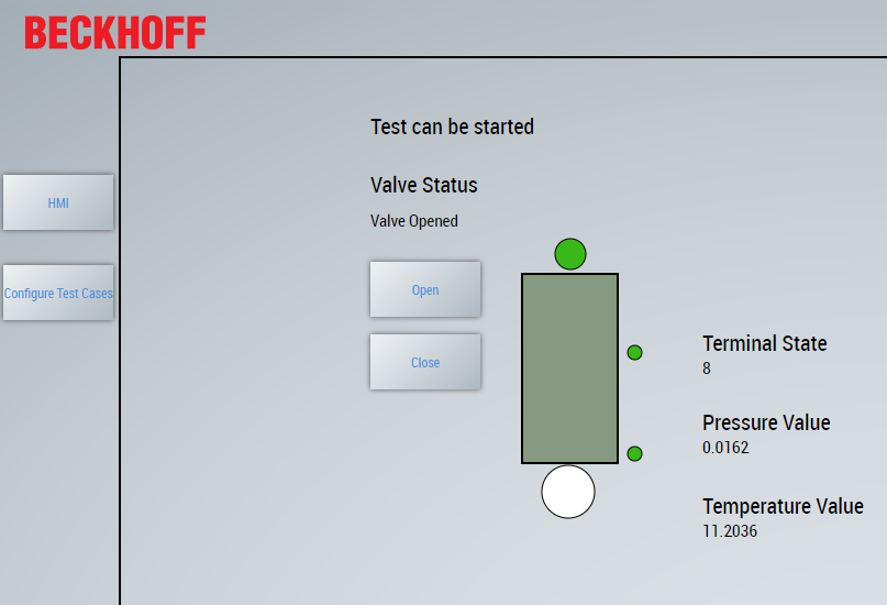
Figure 07: Testing the valve
When we are testing our software, we must select a test case file (from the configuration page) and the test sw should be connected to the PLC.
Testing Result
As we see the terminal state is 8, the output solenoid is ON (top circle), and 2 sensors are active. Also, pressure and temperature have some value as specified. This is done and tested in the ideal case. If we press open, the valve will be opened and when we press the valve will be closed. All are fine.
But now, let’s assume after a few days one of the sensors will be broken. When we run the same test the result will be like the following.
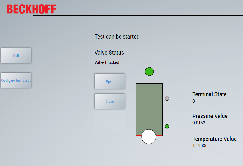
Figure 08: Testing the valve, one sensor is broken (configure a limit switch as OFF)
At this point, your user (operator) fixed the broken sensor and he wants to recover it himself. if he presses Open, Close nothing will help. The only way to make it working restarting the PLC. So the big question is, could we have done the test already beforehand so we could have better software? Yes, we have a solution for that. There are many ways to handle the case. The following is one of the ways to handle it. We introduce a reset button and change the PLC code to handle it so that if such a situation occurs then the operator can manage it without restarting the PLC or calling the developer.
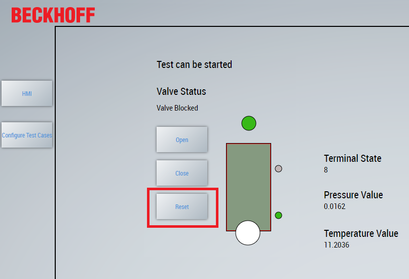
Figure 09: Testing the valve, reset button and it’s functionality has been introduced in the PLC
The following code snippet has been introduced in the PLC. Note there are many different ways to handle the case, but this is one of those. You can download both versions from the download section.
IF state > VALVE_INIT THEN
	IF valveResetCommand= TRUE  THEN
    valveResetCommand := FALSE;
    valveOpenCommand := FALSE;
    state :=VALVE_CLOSED;
    solenoidOutput := FALSE;
    valveCloseCommand:= FALSE;
    upperProximitySensor := FALSE;
    lowerProximitySensor := FALSE;
    stateInit := FALSE;
    pressureRawValue := 0;
    temperatureRawValue := 0;
    terminalState := 0;
    pressureRealValue := 0.0;
    temperatureRealValue := 0.0;
	END_IF
	IF state= VALVE_CLOSED  AND valveOpenCommand= TRUE  THEN
		state :=VALVE_OPENING;
		valveOpenCommand:= FALSE;
		solenoidOutput := TRUE;
		stateInit := FALSE;
	END_IF
	IF state= VALVE_OPENED AND valveCloseCommand= TRUE  THEN
		state :=VALVE_CLOSING;
		solenoidOutput := FALSE;
		valveCloseCommand:= FALSE;
		stateInit := FALSE;
	END_IF
END_IF
Architecture of the Test System
In the following figure, we can see the architecture of the test system. The system use the ADS library provided by Beckhoff.
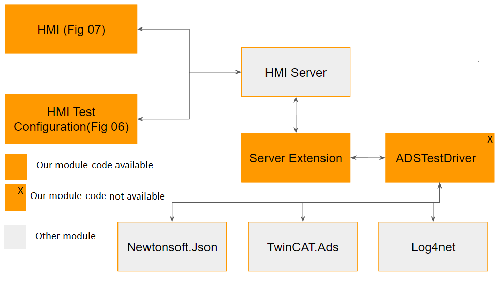
Figure 10: Architecture of the test system
ADSTestDriver is a DLL that we wrap with the extension module. Since the source code is unavailable to you if you find any issue please get in touch with us and we shall update it and deliver it to you for free.
YouTube Video
Coming soon…
Download Source Code
The code contains the server extension DLL and ADSTestDriver.dll. You need to activate the ServerExtension.dll in the Visual Studio project.
The download link for the first version is ValvePLCProject_V01.zip
The download link for the second version (fixed with reset) is ValvePLCProject_V02.zip
Feel free to discuss the test system in our Google group https://groups.google.com/g/hemelix
After unzipping the project you get the following files in the folder ValvePLCProject\ServerExtension\bin\Debug
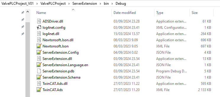
Figure 11: List of binaries provided in the zip files
To run the project directly please follow the following steps:
=> Load the solution in visual studio ValvePLCProject.sln and build the solution
=> First run the PLC program (local or on the remote PLC)
=> Right-click on the ServerExtension (under HMI Configuration Project) and activate the extension
=> Open Desktop.view and load in live view, press on “Configure Test Cases”
=> Press on the connect button, if all are fine we should get the connected check box checked
=> If we press on refresh list, we get the list of filtered variables
=> Now we can configure each output and define what the input variables and analog variables should do
Known Issues
=> Once we have created test cases (configured properties) then we can’t load the test case file and edit it (we need to recreate it again, we shall fix it in the next version)
=> ADSTestDriver, the binary is available in the downloadable project, if you need source code you can contact us!
What next
Download the sample from the link given above.
Next, let’s try to understand how to compare 2 TwinCAT projects: https://www.hemelix.com/plc/twincat-software-project-compare/
Ask questions related to the Hemelix sample code and design on the Google group https://groups.google.com/g/hemelix