Hardwares used in Beckhoff
This page clarifies different hardware used in automation in general with some images. Many electrical components such as fuse, circuit breaker, etc are used in the automation system. We shall not show the details but some overview we shall display which can be helpful for the software development.
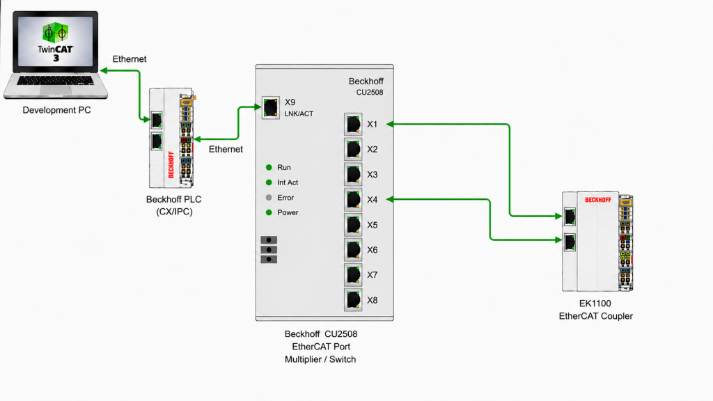
Figure 01: PLC, CU2508 and coupler connection
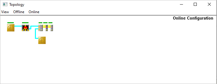
Figure 02: CU2508 port and it’s status
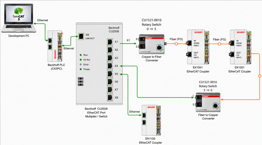
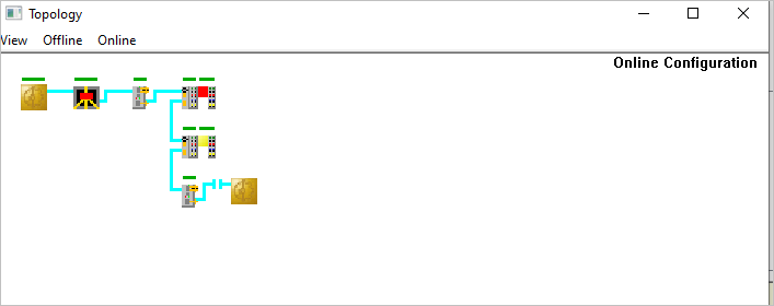
Figure 03: CU2508 port and typical connection (Int Act should blink when working properly, 2 Masters)
The development PC should be connected to a suitable Ethernet port on the PLC. The IP address of this PLC port must be in the same subnet as the development PC.
The second Ethernet port on the PLC should be configured to Obtain IP Address Automatically (DHCP) and connected to the X9 port of the CU2508.
From the X1 port of the CU2508, a copper Ethernet cable can be connected to a copper-to-fiber optic media converter. The fiber optic cable is then connected to the IN port of the EK1500 coupler. From the OUT port of the EK1500, the fiber optic cable can continue to the next fiber optic device in the network.
If a redundant fiber optic ring is required, the OUT port of the last EK1500 coupler can be connected to a fiber-to-copper media converter. The copper Ethernet cable from this converter can then be connected to the X4 port of the CU2508 (or another suitable port) to complete the ring.
As many EK1100 couplers and associated EtherCAT I/O terminals as required by the project can be connected throughout the EtherCAT network.
A number of IO cards can be attached to the coupler. If we have many cards attached, then we need to attached power supply card to feed power to the system.
When we have linked any variable to an IO card’s channel, then the System will go to OP state. If no variable is linked and the system is in RUN mode, the devices will not be in OP state.
Cable Redundancy
Figure 04: Cable redundancy in EtherCAT network
Redundancy Options:
Option 1: Off
Use this if you do not want EtherCAT cable redundancy.
Only one Ethernet port is used by the EtherCAT master.
A cable break will stop communication to the affected part of the network.
Option 2: Second Adapter
Use this if your EtherCAT master has two separate Ethernet ports dedicated to EtherCAT redundancy.
For example:
EtherCAT Master Port A ─────► CU2508 X9
EtherCAT Master Port B ◄──── Return from redundancy port
This is the recommended mode for Beckhoff cable redundancy when the PLC/IPC has two Ethernet interfaces (the return path in the same PLC).
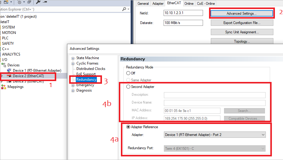
Option 3: Same Adapter (Adapter Reference)
This mode uses one physical Ethernet adapter that supports two logical EtherCAT channels (adapter references).
According to Beckhoff documentation, if the first master is connected to port 1, then the redundancy cable should be connected to 2 (or 3/4, 5/6, etc)
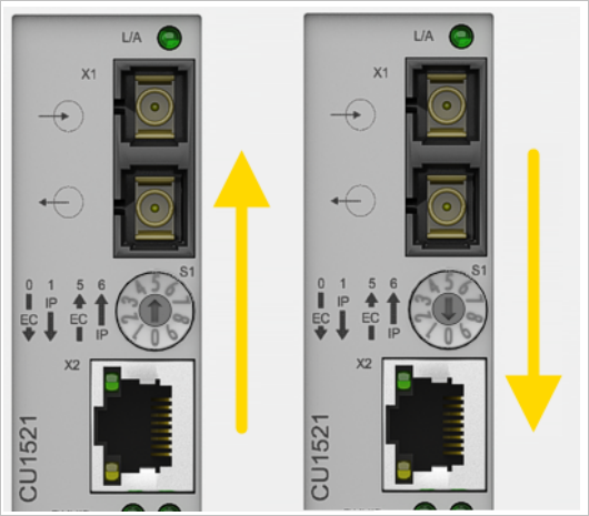
In Figure 3, we have used option 3. We have 2 CU1521 devices, one for forward conversion, Ethernet to fiber optics with rotary dial settings 0 to 5, and the other one returning path, has another CU1521 device with rotary dial settings 5 to 0, fiber optics to Ethernet.
Check the manual page 33
https://download.beckhoff.com/download/Document/io/infrastructure-components/cu15x1_en.pdf

Figure 05: Media converter CU1521 (forward and return path)
Reorganising Network
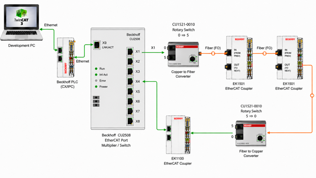
Figure 06: Reorganising the network, EK1100 is part of the single master.
The above image is reorganised. The EK1100 coupler is placed after the second converter. This is almost the same as Figure 03, but now we have a single master.
Single EK1100
Figure 07: Reorganising the network, EK1100 is part of the single master.
The above image is reorganised. The EK1100 coupler is connected and back to X4
Testing the Cable Redundancy
We tested the network by having an input switch connected to the coupler. We disconnected one connection at a time and saw that the input signal gives a valid value.
Figure 03 =>Sample LoopTest1
Figure 06 =>Sample LoopTest2
Figure 07 =>Sample LoopTest3
Figure 08: Redundancy test, Figure 3 has been reorganised as Figure 06
Figure 08 =>Sample LoopTest2
Figure 09: Redundancy test, Figure 6 has been reorganised as Figure 07
Figure 09 =>Sample LoopTest3