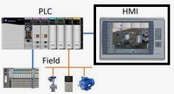
TwinCAT HMI with PLC Program
We have installed the necessary tools and created Hello HMI project according to https://www.hemelix.com/scada-hmi/twincat-hmi/my-first-twincat-hmi/. Now we need to link the program so that it will read data from the PLC. In real life, the data will come from field devices such as a valve, pressure sensor etc.
The simple application will read an integer variable from simulated PLC (TwinCAT can simulate the development computer as a PLC, basically it means mostly we don’t need to have an actual PLC device for running or learning the sample provided) with a 1-second interval and write a string value to the simulated PLC. We shall show all the necessary steps.
Download the sample HelloTwinCATHMI.zip
=> Fire your visual studio
=> File | New project
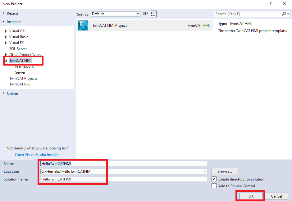
Figure 1. Creating our first TwinCAT HMI application
=> Make the toolbox visible (View | ToolBox Or Ctrl+Alt+X) , Tool box should be visible.
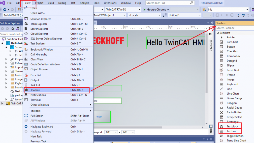
Figure 2. Toolbox and control in the Visual Studio
=> Drag and drop, 2 Textblocks (for displaying text and it does not offer editing in the GUI), 1 Textbox (allow to edit and display), and a button, reposition (select the control and move around by keeping the mouse left button down) those controls (Controls are UI elements that determine how data, text, images, and other information appear on the user interface) to the Desktop view.
=> Change the text of one of the text blocks to “Hello TwinCAT HMI” and position it on the top, in the same way change the text of the Button from “Button” to “Write”.
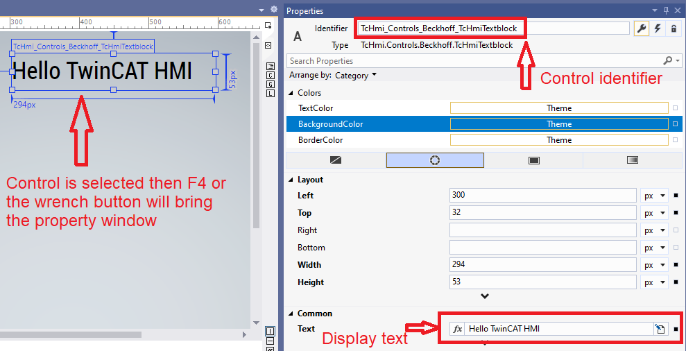
Figure 3. Control selection and identifier
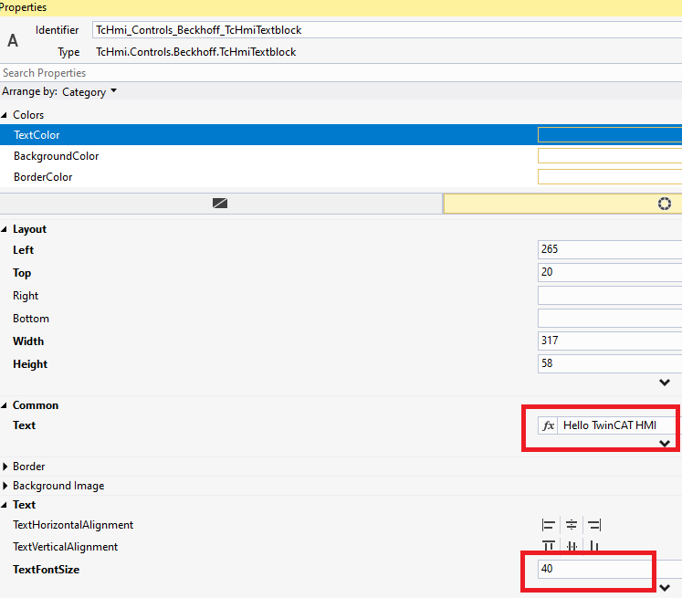
Figure 4. Display font selection
=> The HMI is ready now and it should be like the following. If you press on the live view you can see it is running. On the other hand, you can press on the browser to load and run inside the browser.
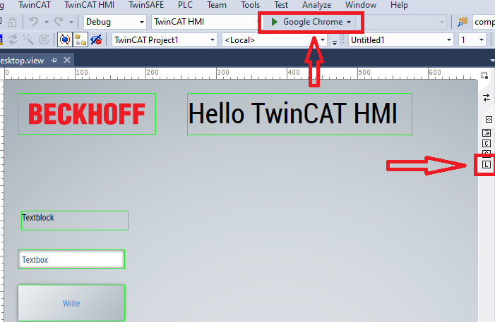
Figure 5. The HMI can be tested in the browser or by the Live view
Though our HMI is ready it is not doing anything interesting, so we shall create a small PLC program (that will run in the TwinCAT PLC simulator in my development computer).
=> Select the solution explorer in Visual Studio and then right-click | Add | New Project (See for details https://www.hemelix.com/automation/first-plc-program/), default name should be fine.
=> Open the MAIN(PRG) file and copy-paste the header part to the upper part of the file and lower part to the lower part of the file.
//Header of the program
PROGRAM MAIN
VAR
myStringWriteValue : STRING := '';
myIntReadValue : INT := 0;
myTimer : TON;
END_VAR
//Body of the program
myTimer(IN := TRUE, PT:= T#1S);
IF myTimer.Q THEN
myIntReadValue := myIntReadValue +1;
IF myIntReadValue > 10000 THEN
myIntReadValue:= 0;
END_IF
myTimer(IN:= FALSE);
END_IF
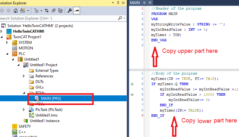
Figure 6. A small PLC program for generating numbers with timer
=> Run the PLC Program by pressing the activate configuration, check if we have any error (hope not!). See the following screenshot to be familiar with the Visual Studio TwinCAT user interface.
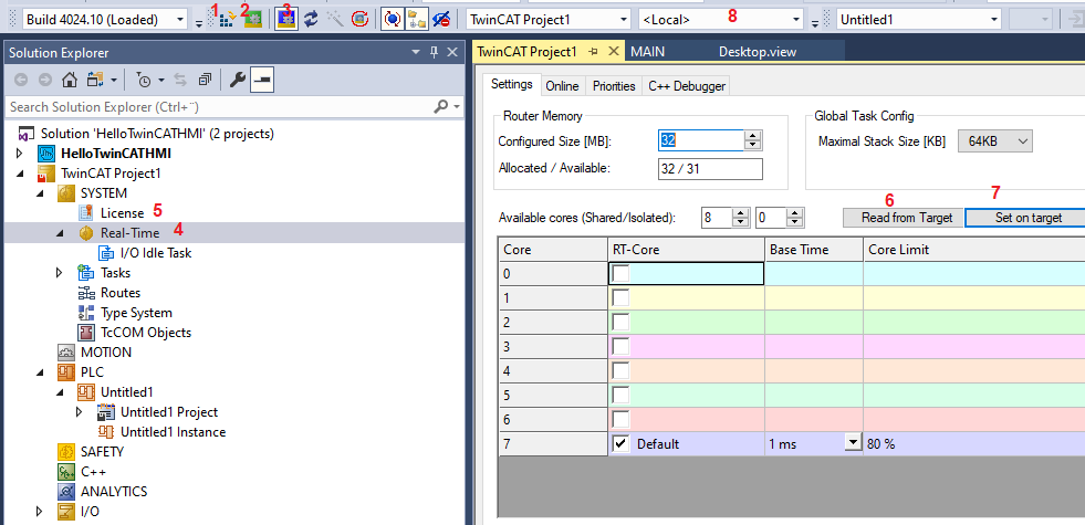
Figure 7. We need to set the core for PLC
1 => Activate the program (including download to the target either PLC hardware or simulator) after these programs are executed.
2 =>Target is switched to run mode, in this mode programs are executed.
3 =>Target is switched to config mode, in this mode programs are not executed and it allows configuration of the program, such as scanning I/O cards, etc.
4 => Configure the core of the hardware.
5 => Allow to insert license for the TwinCAT Software, we can activate 7 days license freely.
6 => Read the number of cores in the PLC or simulator (if running in the development computer)
7 => Set the core in the PLC or simulator (if running in the development computer) where the program will be executed
8 => It allows us to select where we should run the program to a simulator (local PC, IP address is 127.0.0.1)
=>If you run the PLC program you can see that myIntReadValue is increasing 1 in each second, now we display those data to the HMI
=> Select HMI project then TwinCAT HMI | Windows | TwinCAT HMI Server Configuration and press on Accept as shown in the following image.
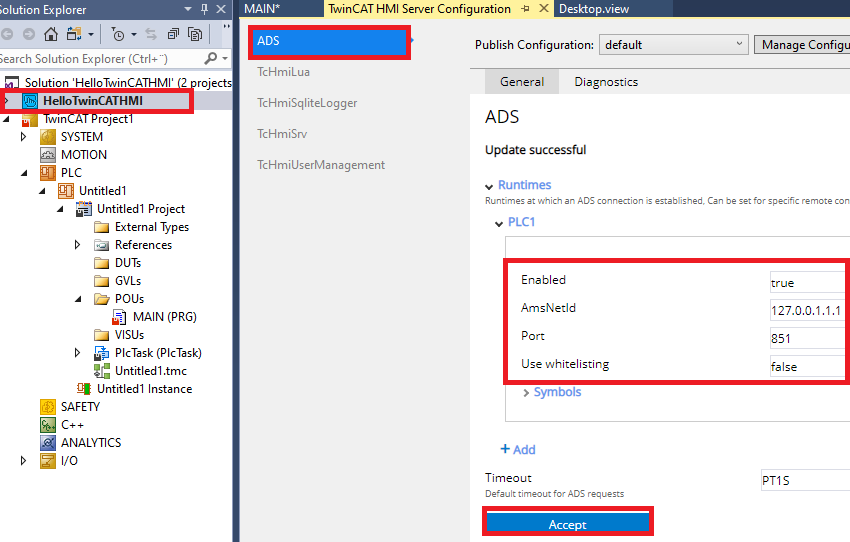
Figure 8. We tell HMI what is address of the PLC (normally identified by AMS Net ID)
=> Now press on the TwinCAT HMI | Windows | TwinCAT HMI Configuration then All Symbols | Expand ADS
=> Double Click on the myIntReadValue and myStringWriteValue to map those variable, it will be as shown in the following image
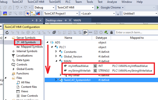
Figure 9. Mapping of variables which we are going to show in the HMI
=> Now come back to the Desktop view and press on the other text block and then bring the properties window (F4 or the range icon), follow the screen step 1 to 4. When you are in step 2 you need to select Create Data Binding.
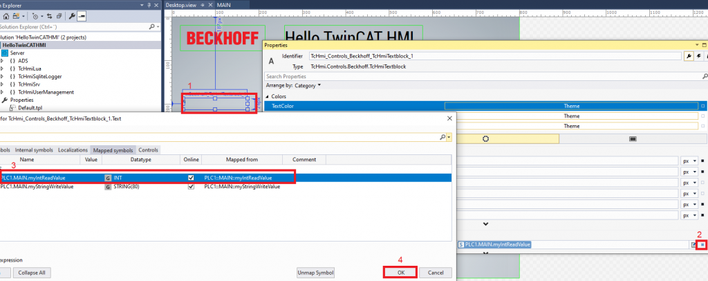
Figure 10. Linking of mapped variables so these can be displayed on the UI
=> Run the PLC Program by pressing the activate configuration (if not running) and you should see the decimal numbers in increasing order is being displayed (you have to run in the browser or with the Live View).
Now we want to get the typed value from the textbox and want to write to the other variable myStringWriteValue.
=> Select the Write button and bring the properties window, in the property window press on the event icon (lightning bolt)
=> On pressed event click on the edit actions and conditions
=> From the left pane drag and drop the WriteToSymbol (on the left side select the server symbol myStringWriteValue)
=>On the right side select the text box then common properties and text. We are telling the framework that takes the text from the edit box and writes it to the PLC string variable.
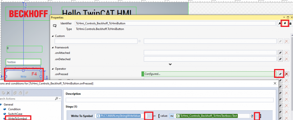
Figure 11. Writing to a PLC variable from the HMI control
Final view is like the following, see that value in the field is changing in each second and if you press on the Write button that text will be written to the variable myStringWriteValue
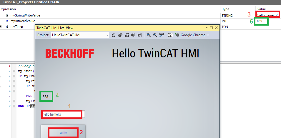
Figure 12. Final view of the HMI, as we see data are being exchanged between HMI and PLC
Tips:
01
You may have noticed each control has a unique identifier, for example, TcHmi_Controls_Beckhoff_TcHmiTextblock is the identifier of the text block “Hello TwinCAT HMI” and TcHmi_Controls_Beckhoff_TcHmiTextblock_1 is the identifier of other text blocks where we display the integer variable from the PLC. It is a good idea to rename it to a more expressive one. The framework adds _1, _2, etc based on the order we do drag and drop.
02
If we don’t see the symbols from ADS in all symbols and there are warnings in mapped symbols (when we try to map) then do the following.
You were probably running another project on your PLC, current program must be activated first.
You could try also the following:
=> Restart Visual Studio
=> Activate the PLC program again (the hello TwinCAT)
Download the sample code from the link given above.
See next our Linear Gauge example at https://www.hemelix.com/scada-hmi/twincat-hmi/linear-gauge-example/
Ask questions related to Hemelix sample code and design at Google group https://groups.google.com/g/hemelix