TwinCAT HMI User Control
Controls
Controls are UI elements that determine how data, text, images, and other information appear on user forms for both display and user input. Each control type has a unique look and provides different functions for users. The system assigns a default control when you define a new field.
In TwinCAT HMI, all visual elements are controls. We drag and drop individual controls from the toolbox (View | Toolbox in Visual Studio) to the desktop and build a useful application. Each control is identified by a unique identifier. We can get a reference to that control by JavaScript code and change it dynamically. Here are a few examples, this is the beauty of TwinCAT HMI.
// Get a reference to Desktop
var desktop = TcHmi.Controls.get('Desktop');
//Get a reference to rotate button
var rotateButton = TcHmi.Controls.get('TcHmiButton_Rotate');
if(rotateButton) {
    //Change the button text
    rotateButton.setText('New Button Text');
}
We get a reference to a control and use JavaScript to manipulate it as we need.
Controls provided by Beckhoff
TWinCAT SDK provides controls which can be seen in the Visual Studio ToolBox (View | ToolBox or CTRL+ ALT+X)
Line: for drawing a vertical or horizontal line
Horizontal Line => to make a 200 pixel line (X1, Y1, X2, Y2) => (0,0,200,0) and width 200, Height 2
User Controls
User controls are simple to create and are frequently used to develop particular UI scenarios. For instance, a user control that represents a contact form that has text boxes for the user’s name, address, and phone number may be developed. The application might then use this user control whenever a contact form is required. The major principle here is that whenever we want to use something frequently then we can build it as usercontrol. This can be a calibration dialog for different machines.
In TwinCAT HMI, user control is a control that is created by the user. As an example, a button that we find in the toolbox is a user control but it is a system control provided by the TwinCAT HMI framework. User control is made by using multiple system controls. We can make a composite control (by reusing system control as many as needed). Then the composite control will be reused as many times as needed. This is like a class in software engineering where we can create an instance of it as many times as needed. Each instance can have different properties for each class member. A User Control is an object type of its own. A user control should have at least one system control. By using user control we can conveniently instantiate an array of objects from the PLC where each item represents a device with different properties. We use them to group a set of controls and behaviors together in a reusable way.
// Get a reference to user control with an identifier MyUserControl_1
var myUserControl = TcHmi.Controls.get('MyUserControl_1');
//Get a reference to a image control that is a control of the user control
//MyUserControl_1.TcHmiImage_InUserControl => usercontrol identifier.image identifier
var imageInsideUserControl = TcHmi.Controls.get('MyUserControl_1.TcHmiImage_InUserControl');
if(imageInsideUserControl) {
    //Change the image to a new image
    imageInsideUserControl.setSrc('Images/Beckhoff_Logo.svg');
}
A user control can be designed by the following steps:
Click here to download UserControl_Hemelix.zip
The example has a Lock (a device that can be used to lock the door), MainDoor (the main gate to enter the yard), and a water valve. All these devices have a name and IsClosed boolean variables. These common properties will be displayed by the user control. As we see all four components are similar looking but they have different images, text, and status. We are making instances and configuring them with different symbol expressions.
The sample application will have the following default view.
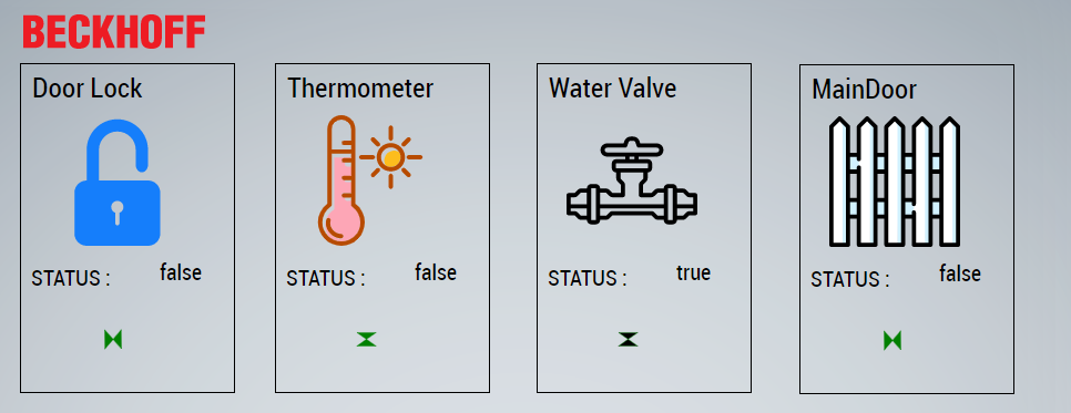
Figure 01: Statues of 4 devices of our fictitious home automation system.
We are displaying four different kinds of device status in the HMI. Each device has a name, icon, status text and some symbol to indicate visual status. We have designed a single-user control and we have created four instances of it. The name and the status are reading from the PLC directly. Device images are supplied as parameters to the user control. Status symbol is loaded by JavaScript code.
How to create a user control in TwinCAT HMI Engineering
Creating a user control in the engineering environment is very easy. If we follow the STEPS and watch the video then it will be clear and we shall be able to create any kinds of usercontrol after this.
STEP 01: Fire our Visual Studio and create a TwinCAT HMI project (File | New Project | TwinCATHMI | TwinCATHMI Project). We have the following empty HMI

Figure 02: Empty desktop view after creating with the visual studio
STEP 02: Create a folder in the solution explorer and name is as UserControl. Select project in the solution explorer and right click then add new folder
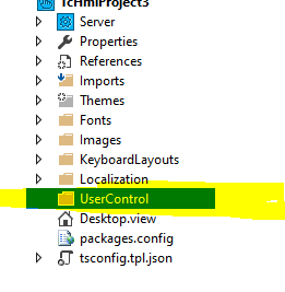
Figure 03: Folder creation in the Visual Studio Solution explorer
STEP 03: Right click on the UserControl folder and select Add | New Item this will bring the following screenshoot. Give a suitable name and press Add.
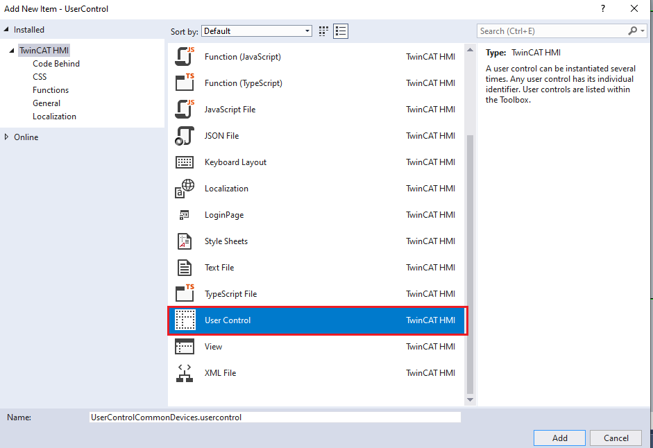
Figure 04: Inserting user control into the solution explorer
The empty user control has been created where we can decorate it, we can see our control (UserControlCommonDevices.usercontrol and its parameter UserControlCommonDevices.usercontrol.json). UserControlCommonDevices.usercontrol.json is a JSON-based dialog where we can insert the needed parameters for the usercontrol.

Figure 05: Inserted user control and it’s properties
STEP 04: Bring toolbox (View | Tool Box or Alt + CTRL + X)
STEP 05: Decorate the user control by using required Beckhoff control as shown in the following image.
STEP 06: Give a suitable expressive name for the identifier field in the Beckhoff image control
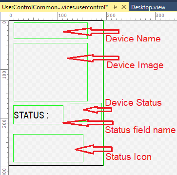
Figure 06: Decoration of user control with basic controls
STEP 07: Click on the UserControlCommonDevices.usercontrol.json file in the solution explorer, this will open a dialog where we can configure the parameter name, Datatype, default value etc.
STEP 08: We change the device name Datatype to string and DeviceImage to Path as shown in the following image.
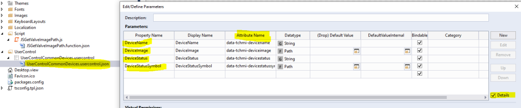
Figure 07: Configuration of user control parameters
STEP 09: Drag and drop UserControlCommonDevices.user control file from the solution explorer 4 times and arrange those side by side as shown in our final HMI image.
STEP 10: Now we need to do the server configuration (we tell HMI from where to fetch data, in this case from our local PLC)
STEP 11: Run the PLC to local mode or to a PLC and press TwinCAT HMI | Windows | TwinCAT HMI Server configuration
STEP 12: Configure according to the image below and finally press on the accept button, if you are running the program to remote PLC see the link for more https://www.hemelix.com/automation/structured-text-how-to-add-route-for-plc/
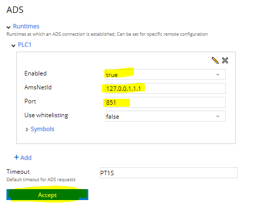
Figure 08: ADS configuration, from where or which PLC will provide data to HMI
STEP 13: Create a folder called Script in our solution explorer and rename it as Script and add a JavaScript file rename it for example JSGetValveImagePath.js
STEP 14: Copy the content from the code below and configure as shown in the following image
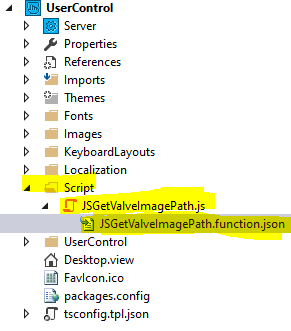
Figure 09: JavaScript function creation with parameters
STEP 15: We shall pass the isClosed variable and DeviceType parameter to JavaScript function, based on this we shall find a status image for showing it to the HMI, copy paste the code to the JS function.
STEP 16: Configure the JavaScript function’s parameters as shown in the following image.
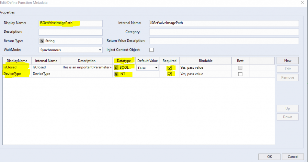
Figure 10: JavaScript function parameters edition
STEP 17: Copy the related images to the image folders
STEP 18: Configure each user controls by passing DevieName, DeviceImage, DeviceStatus and DeviceStatusSymbol (this is returned by the JavaScript function)
STEP 19: Press on the right side small rectangle to configure the parameters.
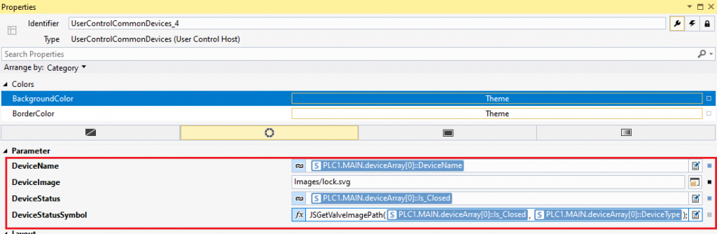
Figure 11: Calling JavaScript function
Download the project and code
Please download the sample and try! There are 2 projects in the solution. 1 PLC project and another HMI project. The status is displayed from the PLC to the HMI.
The JavaScript code:
// Keep these lines for a best effort IntelliSense of Visual Studio 2017 and higher.
/// <reference path="../../Packages/Beckhoff.TwinCAT.HMI.Framework.12.742.0/runtimes/native1.12-tchmi/TcHmi.d.ts" />
(function (TcHmi) {
    var Functions;
    (function (Functions) {
        var MyNamespace;
        (function (MyNamespace) {
            function JSGetValveImagePath(IsClosed, DeviceType) {
                var returnamenpath = '';
                switch (DeviceType) {
                    case 0:
                        if (IsClosed == true) {
                            returnamenpath = 'Images/pipehor_closed.svg';
                        }
                        else {
                            returnamenpath = 'Images/pipehor_open.svg';
                        }

                        break;
                    case 1:
                        if (IsClosed == true) {
                            returnamenpath = 'Images/pipever_closed.svg';
                        }
                        else {
                            returnamenpath = 'Images/pipever_open.svg';
                        }
                        break;
                    case 2:
                        if (IsClosed == true) {
                            returnamenpath = 'Images/pipever_closed.svg';
                        }
                        else {
                            returnamenpath = 'Images/pipever_open.svg';
                        }
                        break;
                    case 3:
                        if (IsClosed == true) {
                            returnamenpath = 'Images/pipehor_closed.svg';
                        }
                        else {
                            returnamenpath = 'Images/pipehor_open.svg';
                        }
                        break;
                    default:
                        break;
                }
                return returnamenpath;
            }
            MyNamespace.JSGetValveImagePath = JSGetValveImagePath;
        })(MyNamespace = Functions.MyNamespace || (Functions.MyNamespace = {}));
        Functions.registerFunctionEx('JSGetValveImagePath', 'TcHmi.Functions.MyNamespace', MyNamespace.JSGetValveImagePath);
    })(Functions = TcHmi.Functions || (TcHmi.Functions = {}));
})(TcHmi);
The PLC Code:
//Function block header
FUNCTION_BLOCK FN_DEVICES
VAR_INPUT
	Enabled : BOOL;
	DeviceType : SINT;
END_VAR
VAR_OUTPUT
	Is_Closed : BOOL;
	DeviceName : T_MaxString;
END_VAR
VAR
	myTimer : TON;
	counter : UINT := 0;
	timeInterval : TIME;
END_VAR
//Function block body
(*
If the device is enabled  then the program generate IsClosed to false from true and vice versa to simulate UI and the device.

Device name and their type
Name 			type
Lock  			0    ->   Every 200 miliseconds interval changes the status
Thermometer		1    ->   Not valid as there is no IsClosed variable
Water Valve 	        2    ->   Every 400 miliseconds interval changes the status
MainDoor		3    ->   Every 500 miliseconds interval changes the status
*)

	CASE DeviceType OF
		0:
		timeInterval := T#200MS;
		DeviceName := "Door Lock";

		1:
		timeInterval := T#300MS;
		DeviceName := "Thermometer";
		;

		2:
		timeInterval := T#400MS;
		DeviceName := "Water Valve";

		3:
		timeInterval := T#500MS;
		DeviceName := "MainDoor";
	END_CASE

myTimer(IN:= Enabled, PT:= timeInterval);
IF myTimer.Q = TRUE  THEN
	myTimer(IN:= FALSE);
	IF Is_Closed = TRUE THEN
			Is_Closed := FALSE;
		ELSE
			Is_Closed := TRUE;
	END_IF
END_IF
Tips:
01: How to hide/collapse a control
=> Get a reference to the control
=> Call setVisibility(‘Visible’ | ‘Hidden’ | ‘Collapsed’)
Keywords as strings.
‘Visible’ is the normal display
‘Hidden’ hides the element, which nevertheless still occupies the allocated space.
‘Collapsed’ hides the element, which then no longer takes up any space. We can call setVisibility(‘Visible’) and works again.
var angleControl = TcHmi.Controls.get("TcHmi_Controls_Beckhoff_TcHmiTextbox_Angle");
angleControl.setVisibility('Hidden');
02: Sometimes, we press a button, but the data does not go to the PLC
If it does not harm to rewrite it, we can write it again. This will make sure the data is written to the PLC
Download the sample from the link given above.
Next, let’s try to understand container user control at https://www.hemelix.com/scada-hmi/twincat-hmi/twincat-hmi-compound-user-control/
Ask questions related to Hemelix sample code and design at Google group https://groups.google.com/g/hemelix