Linear Gauge Example
First Example (Linear guage)
A YouTube video is available at the end of the page.
We assume that the necessary software is installed. We shall build a project and test and publish it to a remote HMI server.
This is a simple example we read data from a pressure sensor and display it on a gauge. We don’t have a real pressure sensor here but we shall simulate a pressure sensor by using a PLC program. The PLC program changes the value from 0.000 to 100.00 and then comes back to 0.000. It just repeats the value and HMI display it. Data accusation can be started by pressing the Start button and can be stopped by pressing the Stop button. The button’s text is changed based on the context.
Download the complete source code Linear_Guage_Hemelix.zip and run it in Visual Studio.
There is another button Set Value, if we press this button it will read the value from the text box and set this value as pressure value to the PLC. If we are reading the value at the same time, we can’t see the effect, so better we stop the PLC by pressing the stop button and then set the value.
STEP 1: Start Visual Studio and open a new TwinCAT HMI project.
STEP 2: Select Tool Box (if not visible select View | Tool Box)
STEP 3: Drag and drop the Linear gauge on the desktop view, make one of those vertical (properties | appearance | orientation)
STEP 4: Drag and drop a couple of buttons and a textbox (not textblock) and rename those as shown in the following image.
The linear gauge example final one is shown below. If we press on the Start button then it will start reading the pressure sensor and display on the left side linear gauge. The Start button will be changed to Stop/Start. If the PLC is already running then it will show the status of the variable and set the text as needed.
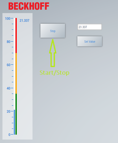
Figure 01: The linear gauge HMI
PLC Source code behind the HMI
Since we don’t have an actual pressure sensor, we are using a small piece of structured text code for generating the pressure sensor values. That pressure value is shown on the linear gauge. When the startTimer variable is TRUE then the timer will start and generates data (pressure value), the pressure value is shown on the Beckhoff HMI.
//Declaration, header of the program
PROGRAM MAIN
VAR
pressureValue : REAL := 0.0;
myTimer : TON;
startTimer : BOOL := FALSE;
directionPlus : BOOL := FALSE;
END_VAR

//Body of the program
myTimer(IN:= startTimer, PT:= T#50MS);
IF myTimer.Q = TRUE THEN
	myTimer(IN:= FALSE);
	IF pressureValue >= 100.0 THEN
		pressureValue := 100.0;
		directionPlus := FALSE;
	END_IF
	IF pressureValue <= 0 THEN
		pressureValue := 0.0;
		directionPlus := TRUE;
	END_IF
	IF directionPlus = TRUE THEN
		pressureValue := pressureValue + 1.123;
	ELSE
		pressureValue := pressureValue - 1.321;
	END_IF
END_IF
If you don’t know how to run the PLC program in a windows environment, please take a look at this page https://www.hemelix.com/automation/first-plc-program/
HMI and the simulator PLC code relation
We shall explain how PLC variables are linked to the HMI. On the left side, we have HMI and on the right side, we have the PLC program. the pressure value is displayed on the HMI in two places (the Linear gauge and the textBox). When we press the Start button the startTimer Boolean variable is set to true and the program starts to generate a pressure value, and the value started to be changed on the UI. On the other hand, if we press on the Set Value then the program will read the value from the text box and ser this value to the pressure value variable.
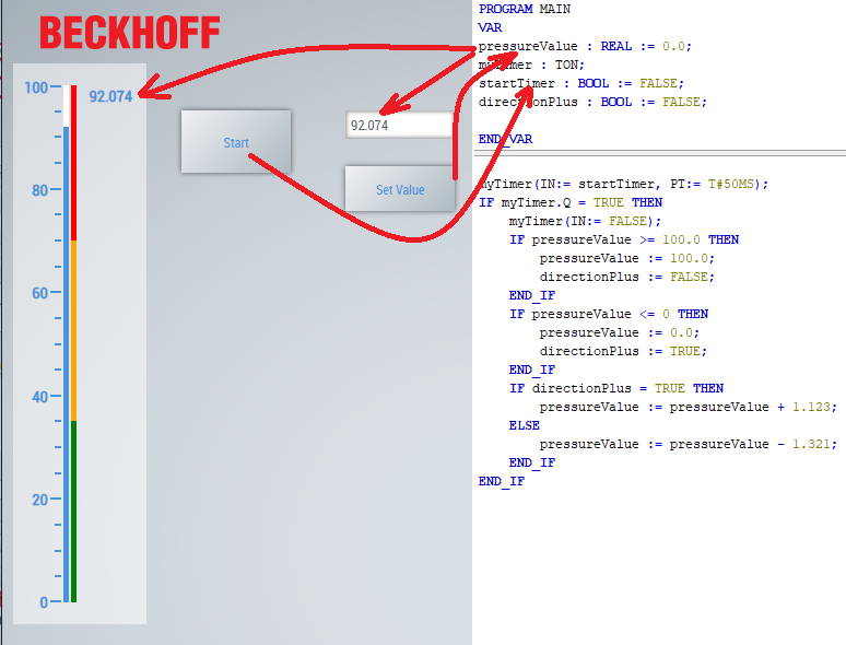
Figure 02: Relation between HMI field and the PLC program which provides the actual data
Above picture shows pressureValue is linked to Lineargauge and StartTimer is linked to Start button.
How to build the HMI
Few steps are needed before reading the data from PLC (we assume that Button and Linear gauge are placed on the UI)
We need to bring those PLC variables available to the UI project. These are done for us by the framework, we just use those. More will be discussed in the next tutorial (Symbol Data).
First, we need to configure the HMI Server
STEP 1: Select from the Menu TWINCAT HMI | Windows | TwinCAT HMI Server configuration
STEP 2: Click on ADS | Runtimes | PLC1 and make the necessary changes as shown in the following figure. If we want to read from actual PLC, we shall use actual AmsNetId. The PLC should be in the same network (for more see our network tutorial). Finally press on the Accept button.
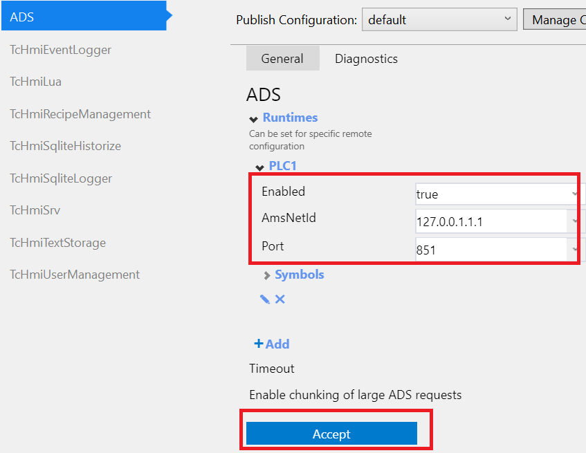
Figure 03: Establishing relation between HMI and the PLC by using ADS protocol
Now we shall have a connection to our PLC but we need to tell the framework which variables we want to manipulate or want to listen. This process is called symbol mapping
STEP 3: Now go back to HMI Configuration Select from the Menu TWINCAT HMI | Windows | TwinCAT HMI configuration
STEP 4: Select Server Symbols | All Symbols | then expand the ADS | PLC1 | MAIN | Map Symbol
STEP 5: Select pressureValue and startTimer variables and map them, these will be added to Mapped Symbols
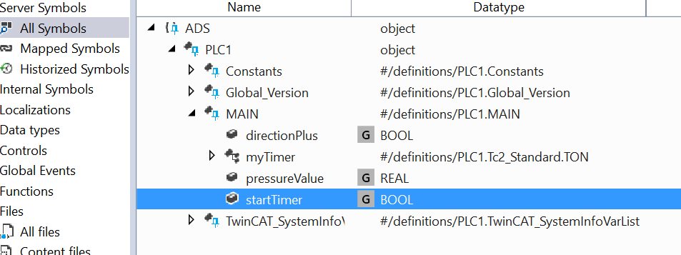
Figure 04: Mapping a variable so that can be available in the HMI
Now let’s configure the button
STEP 6: Go to button events and pressed on the edit icon, drag and drop General | Condition to the right pane. Drag and drop WriteToSymbol to the THEN box and to ELSE box
STEP 7: Select small square and Create data binding
STEP 8: Insert the Text field (selected control | Start | Common | Text) and the value to STOP, this will indicate if the startTimer is TRUE then the button text will be Stop (more in the localizations tutorial)
Final STEPS: Do the same for .onPressed for the button and for value for the linearGauge case as shown in the next few images. If you press on the Live view or debug with google chrome we see that value changes when we press the start button and stop when we press the stop button. HMI will get data from the PLC program, so you need to run the PLC program.
Following figure shows how to configure the text of the button when the button is created by the framework. This is good place to check or set the text of a button or similar control.
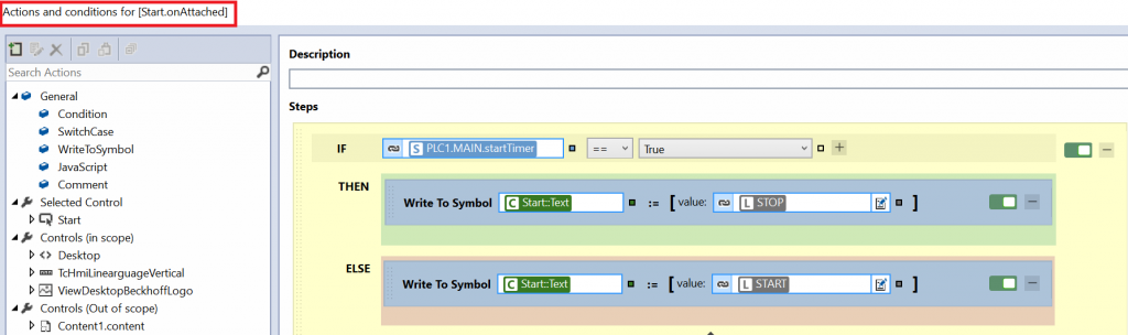
Figure 05: Toggle the content of a button
Following figure shows how to configure onPressed event for button. Write To Symbol statements are used 2 times in if branches.
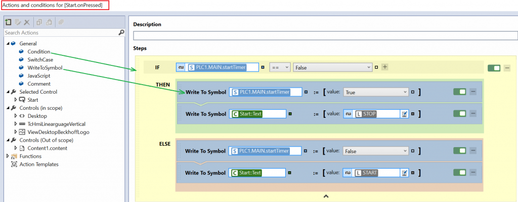
Figure 06: Toggle the content of a button and changing the timer
Value property of the lineargauge has been configured to the pressureValue variable in PLC
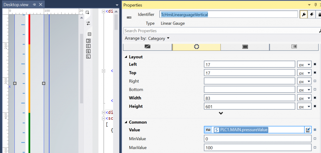
Figure 07: Configure the PLC pressure values from PLC to HMI
Now we shall show how JavaScript has been used in this example, The following expression is available in the value part. It takes the string from textBox and parses it to Float and writes to the variable PLC1.MAIN.pressureValue. parseFloat() is a standard JavaScript function provided by the TwinCAT framework. For more please see our JavaScript tutorial at https://www.hemelix.com/scada-hmi/twincat-hmi/twincat-javascript-function-and-code-behind/.
parseFloat(%ctrl%TcHmi_Controls_Beckhoff_TcHmiTextbox::Text%/ctrl%)
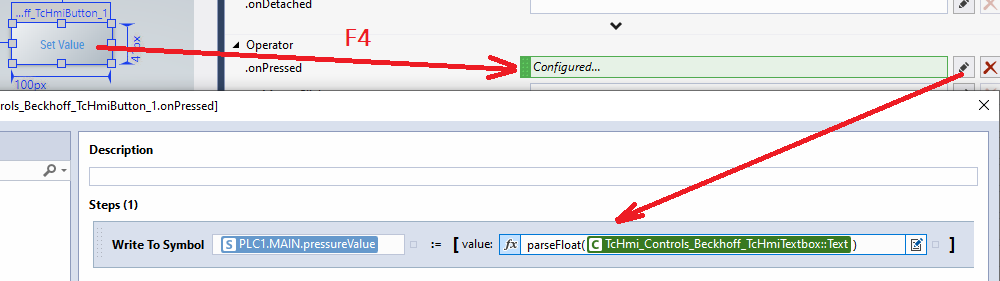
Figure 08: Writing the value from HMI to PLC
In the following image, we can see how the edit box’s text properties has been manipulated. It takes the pressureValue from PLC and makes a 3 decimal text and displays on the UI.
(%s%PLC1.MAIN.pressureValue%/s%).toFixed(3)
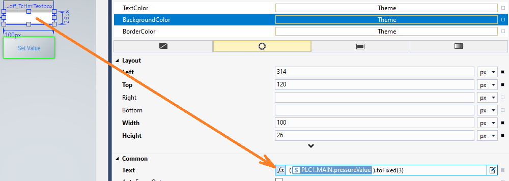
Figure 09: Limiting the value up to 3 digits.
Watch the Video
TIPS
=>How to control data acquisition interval between HMI and the PLC or the OPC UA Server
The default data acquisition interval between HMI and the ADS is 500 ms. The scale mode is none. These can be changed as shown in the following diagram.
Open the properties of the HMI project and change the value (select project, not solution, and press F4).
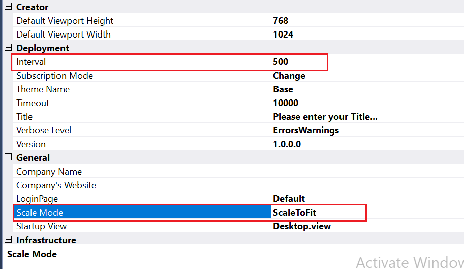
Figure 10: Mode settings for the HMI
Scale Mode: Scaling mode of the HMI. This setting only applies if the Viewport is configured with absolute values (pixel specifications).
ScaleToFit: The width or height of the HMI is scaled to the current size of the browser window without a scrollbar appearing.
ScaleToWidth: The height is scaled accordingly to the width (while maintaining the aspect ratio with scrollbar).
ScaleToHeight: The width is scaled accordingly to the height (while maintaining the aspect ratio with scrollbar).
ScaleToFill: The height and width are stretched to the maximum width and height of the browser window (the aspect ratio is not maintained).
TIPS
=>How to make data available from the server to the HMI client
In Visual Studio, select TwinCAT HMI | Windows | TwinCAT Hmi server configuration | ADS | Runtimes| PLC1| AmsNetId (Enabled True, Port 851) | Accept
Download the sample from the link given above.
Let’s try to understand Symbol and Binding at https://www.hemelix.com/scada-hmi/twincat-hmi/twincat-hmi-symbol/
Ask questions related to Hemelix sample code and design at Google group https://groups.google.com/g/hemelix