Anatomy of Timer in Structured Text
Timers are used to measure specific time intervals. Timers circuits have different applications in different systems. A timer is a specialized type of clock used for measuring specific time intervals. The timer is used to generate signals for checking or doing specific or periodic task on particular time and/or with some intervals.
=>Create a new project and solution in Visual Studio, the project type should be TwinCAT XAE Project (XML format)
=>Add Standart PLC Project from Plc Template
Now double-click on the MAIN (PRG) and it will open an editor where we can replace it with the following code (by copying and pasting the upper and lower parts of the editor).
The sample increases a counter 1 in each 100MS, when it reaches 20 then it fires the R_TRIG, and twentyCounter is increased.
//Header, upper part
PROGRAM MAIN
VAR
	startTimer : BOOL := FALSE; //if true myTimer starts
	integerCounter : INT := 0; //count upto 20 then reset to 0
	twentyCounter : INT := 0;  //Count how many times it has counted
	myTimer : TON;
	myRTrig : R_TRIG;
END_VAR
//Lower part (body of the program)
myTimer(IN:= startTimer, PT:=T#100MS);
IF myTimer.Q = TRUE THEN
	myTimer(IN:= FALSE);
	integerCounter := integerCounter +1;
	IF integerCounter > 20 THEN
		integerCounter:= 0;
	END_IF
END_IF
myRTrig(CLK:= integerCounter=20 );

IF myRTrig.Q THEN
	twentyCounter:= twentyCounter +1;
END_IF
Now it is programmer’s work to continue from this point building the program according to the requirement. In the above program, we have a Timer that is fired at each 100 MS interval. integerCounter variable is increased by 1 in each 100 MS interval. When this variable is greater than 20 then it reset to 0.
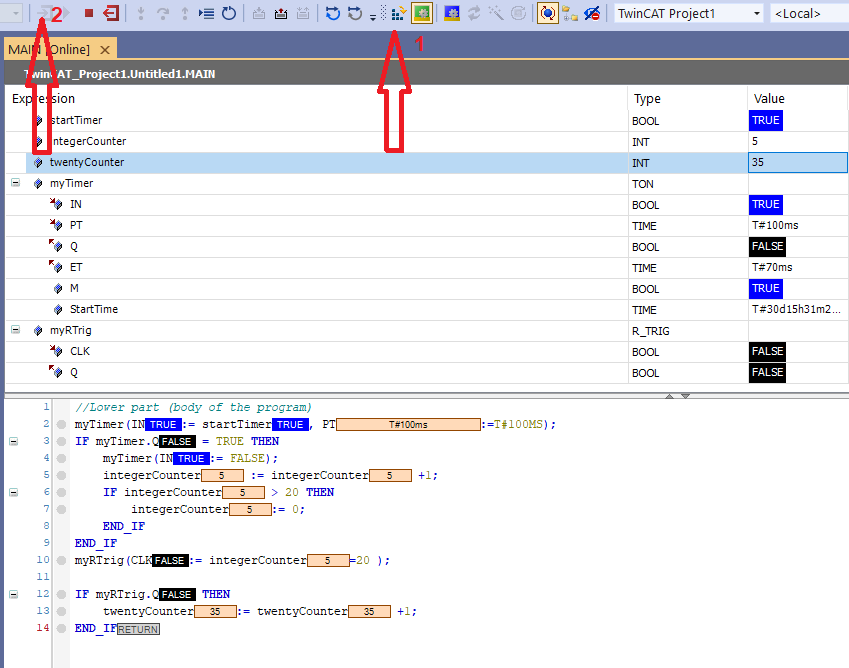
Figure 01: Activation of the PLC program
If we activate the program by pressing activate button in visual studio (arrow 1) and then login to the program (arrow 2) we see the above program running.
Congratulations! you have made your first ST program that is running in TwinCAT simulator.
Now let’s study the timer, what is happening under the hood.
myTimer : TON; //myTimer variable of type TON, TON is a function block
A function block is a POU (program organization unit), which returns one or several values when executed. Typically it has input and output.
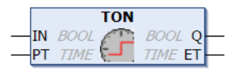
Figure 02: Timer function block
Taken from Beckhoff site
If the Input IN is high then after PT milliseconds the Output Q will be high. ET will be counted in milliseconds until the Q is HIGH. The function block has a boolean input IN and the time PT. If IN is TRUE and after PT time the output Q will be HIGH. When IN goes down then Q goes down as well. ET (elapsed time) can be the maximum PT.
IF IN does not go OFF then Q is HIGH all the time. In each PLC cycle, the program check if the IN has been HIGH or LOW. If IN is LOW, then Q and ET go low, as seen in the following figure.
Inputs:
IN : BOOL type, Starts timer with rising edge, resets timer with falling edge
PT : TIME type, time to pass, before Q is set
Outputs:
Q : BOOL type, Q is TRUE, PT seconds after IN had a rising edge
ET : TIME type, elapsed time, can be used to monitor progress
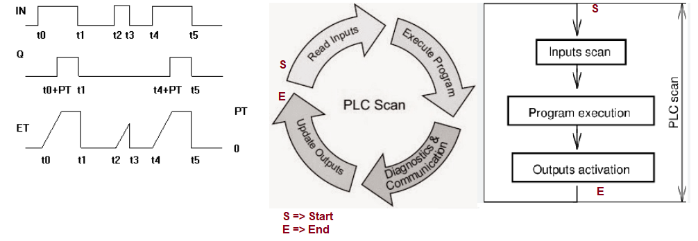
Figure 03: Timing diagram for TON (rising edge timer) and PLC SCAN time
Typically, the PLC program executes each cycle from beginning to end. If there is an input/output statement, it does during the scan time. During the scan time, the PLC program finds IN is HIGH then each cycle ET increase until PT has elapsed. When PT has elapsed then Q goes HIGH. If the IN does not change then Q will be HIGH. When IN goes LOW then Q goes LOW. And in the next cycle if IN goes HIGH then it continues in the same way.
YouTube video:
We modify the original program a bit and insert an HMI project into the solution. If you don’t know the HMI, please take a look at https://www.hemelix.com/scada-hmi/twincat-hmi/twincat-hmi-installation/
PROGRAM MAIN
VAR
timerToggle : BOOL := FALSE;
valuePT : REAL := 1.0;
valueQ : INT := 0;
valueET : INT := 0;
valueCounter: INT := 0;
myTimer : TON;
END_VAR
//Lower part (body of the program)
myTimer(IN:= timerToggle, PT:=REAL_TO_TIME(1000 * valuePT));
IF myTimer.Q = TRUE THEN
	myTimer(IN:= FALSE);
	valueCounter := valueCounter +1;
	IF valueCounter > 30999 THEN
		valueCounter:= 0;
	END_IF
END_IF
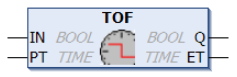
Figure 04: Falling edge timer function block
Difference between TON and TOF is that the output the output Q will be reset after PT milliseconds since IN is reset, as shown in the following figure. If you compare the timing diagram between TON and TOF then it can be clear.
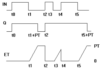
Figure 05: Timing diagram for falling edge timer
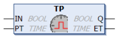
Figure 06: Pulse generator function block
The pulse timer block can be used to generate output pulses of a given time duration.
VAR_INPUT
VAR_INPUT
        IN      : BOOL; (* Trigger for Start of the Signal *)
        PT      : TIME; (* The length of the High-Signal in ms *)
END_VAR
VAR_OUTPUT
VAR_OUTPUT
        Q       : BOOL; (* The pulse *)
        ET      : TIME; (* The current phase of the High-Signal *)
END_VAR
If IN is FALSE, Q is FALSE and ET is 0.
As input IN goes TRUE, tho output Q follows and remains TRUE for the pulse duration as specified by time input PT.
While the pulse output ist TRUE, the elapsed time ET ist increased.
On the termination of the pulse, the elapsed time is held until the beginning of the next pulse, at which point it is reset.
The output Q will remain TRUE until the pulse time has elapsed, irrespective of the state of the input IN.
Graphic Display of the TP Time Sequence:
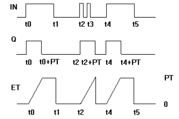
Figure 07: Timing diagram of pulse generator
FUNCTION_BLOCK R_TRIG
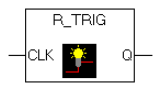
Figure 08: R_Trig function block
Detector for a Rising Edge.
VAR_INPUT
VAR_INPUT
        CLK     : BOOL; (* Signal to detect *)
END_VAR
VAR_OUTPUT
VAR_OUTPUT
        Q       : BOOL; (* Edge detected  *)
END_VAR
The output Q and the help variable M will remain FALSE as long as the input variable CLK is FALSE. As soon as CLK returns TRUE, Q will first return TRUE, then M will be set to TRUE. This means each time the function is called up, Q will return FALSE until CLK has falling edge followed by an rising edge.
This cane be useful when we need to count some variable based on the state change of certain variable.
PROGRAM MAIN
VAR
timerToggle : BOOL := FALSE;
timerToggle2 : BOOL := FALSE;
myTrig : R_TRIG;
variable : INT := 0;
END_VAR
//Body of the program
myTrig(CLK:= timerToggle);
IF myTrig.Q THEN
	variable := variable +1 ;
END_IF
timerToggle2:= myTrig.M;
Whenever the timerToggle variable goes up that is detected by myTrig.Q. F_TRIG (falling edge) is just opposite of R_TRIG (rising edge)
Tips:
01: We can create an HMI application and from the toggle button we can set the startTimer ON and OFF and we can display other variable which can help to do more deep diving.
References:
Download the sample from the link given above.
Next, let’s try to understand user control at https://www.hemelix.com/plc/state-machine-in-structured-text/
Ask questions related to Hemelix sample code and design at Google group https://groups.google.com/g/hemelix