Replacing PLCs for executing the same program
When we are using any PLC, it can break for some reason. Some of the reasons could be for example:
problems with a field device
problems with the power supply
module failure of the input/output (I/O)
PLC can be internally broken (Electronic in the Embedded PC)
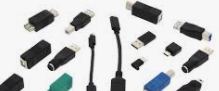
Whatever the reason could be, you need to replace the PLC quickly. If you have exactly the same PLC in hand then you can download the same run time and start using the system again. But say you were running an Intel-based device but you have in hand an ARM-based PLC. It will not work directly since the memory addresses are different. In this article, we address this issue. In the following image, we show some of the different embedded PCs from the Beckhoff site.

Figure 01: Different types of PLCs available in the Beckhoff site
Exchanging Similar PLCs
Even when replacing with an identical PLC, we still need to specify the fieldbus connection point—whether it’s connected to X00 or X01- within Visual Studio. Simply reconnecting the hardware as it was may not be sufficient, especially if the configuration details were not stored in the repository. It’s essential to ensure the system knows where to find the fieldbus interface.
Our sample Hardware Setup
We have a sample program with some hardware. We have a PLC and a coupler is connected to the PLC. We have a similar setup as we have done in the Software Testing section (https://www.hemelix.com/plc/twincat-software-testing/). We change the hardware and make it working by keeping the links.

Figure 02: Hardware setup for the experiment (Coupler and IO cards)
Sample starting IO setup is shown also in the following image. The default PLC program starts with an Intel-based device with IOs shown in the above picture. The adapter configuration is shown below.
PCI is selected EK1200 is configured
OS (NDIS) is selected when a coupler is used, this is also selected when an EtherCAT master is configured within the EtherCAT switch.

Figure 03: Default settings starting with the initial program
PCI bus selection, PCI bus is selected when we select EK1200

Figure 04: PCI bus selection for EK1200
Intel based (CX5010) PLC to ARM based (CX9020) PLC
The default or the start-up setting was done with an Intel-based device, now we would like to replace the PLC with a CX9020 device. Our target is just to replace the PLC while keeping all the functionalities.
Press on the Adapter and search for a compatible device.

Figure 05: Press on the search button to find the right adapter
Before activating with the new adapter do the following.
=> Check the real-time settings
=> Check the license issues
=> Make sure we are in config mode
=> Press activate (in Visual Studio) the program for downloading to the new PLC.
Now our program should work as it was working in the previous PLC
Intel based (CX5010) PLC to ARM based (CX9020) PLC
These steps are exactly the same as the previous one, we just need to find the right address for the ARM ARM-based device. If we don’t set the right address we can’t activate the program, hence it will not run. Even if we set the address wrongly, the program will run but the input/output will not be written to the I/O cards. So the process will not be executed. The following image will show what can happen if we don’t select the right adapter (we have updated real-time settings/license etc). See the fatal error below.

Figure 06: ADS error if right adapter is not set

Figure 07: Intel to Arm based PLC adapter changes
We have shown how to change two different types of PLC, even if we use similar type of PLC for example, one CX version to another, we need find the address/PCI bus correctly.
We can’t activate the program if correct address is not set.
Program may run after activation but the I/O will not happen.
Install Ethernet Driver for using PC as a PLC
The TcRTeInstall tool manages real-time Ethernet compatible devices of the control system. This involves installing a real-time capable driver for the standard Ethernet connection of a control system.
If we install and configure we can directly use any devices to do input output from our PC, it means our PC will work as PLC.
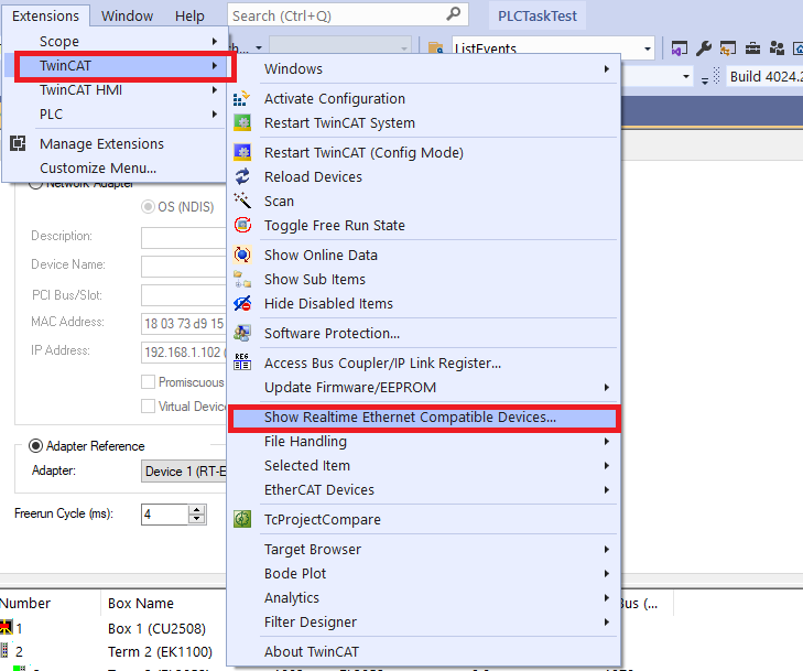
Figure 08: Menu system in TwinCAT environment for ethernet adapter
Alternatively you can install the driver by adding a network capable device to the I/O configuration (e.g. EtherCAT). In the adapter dialog of the network capable device, call the TcRTeInstall application with the button Compatible Devices…:
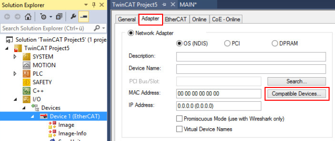
Figure 09: Menu system in TwinCAT environment for ethernet adapter (2nd way)
Call in TwinCAT runtime environments
You can directly call the installation application for the TwinCAT RT Ethernet adapter on a TwinCAT 3 runtime system.
Location: C:\TwinCAT3.1\System\TcRteInstall.exe
Manage network connections
TcRteInstall displays the real-time capable (Compatible devices) and non-real-time capable (Incompatible devices) network interface cards.
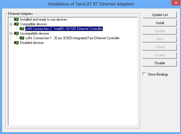
Figure 10: Driver installation for Ethernet Controller
1.Select a real-time capable network interface card from the list of “compatible devices”.
2.Click on the Install button.
The TwinCAT driver for real-time Ethernet and the TwinCAT Ethernet protocol are installed for the selected device.
Now if we connect our PC and Select the Ethernet-TwinCAT-Intel PCI Ethernet Adapter then we can SCAN connected devices (couplers) and if we have terminals connected then we can do input output and control any devices. The follwong pictures show IO list without connected coupler and with a connected coupler (EK1100)
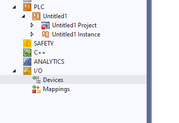
Figure 11: A sample I/O when the coupler is not connected
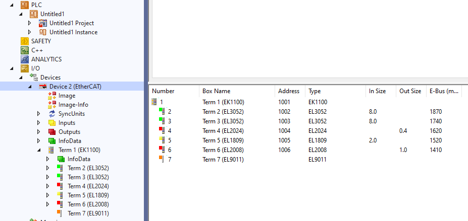
Figure 12: A sample I/O when a coupler is connected with few terminals
Tips:
The target was, say our running PLC is broken (whatever the reason can be), we need to use another type of PLC. In this type of case, we need to change the adapter.
=> We change the PLC
=> After changing the PLC we change the adapter as described above.
=> When we change an Embedded PC then, we can always have an empty project and scan the network which can be compared with the configured devices, which may be helpful.
References:
What Next:
Download the sample from the link given above.
Next, let’s try to understand persistent data https://www.hemelix.com/plc/twincat-3-database-server/
Ask questions related to Hemelix sample code and design at Google group https://groups.google.com/g/hemelix