State Machine
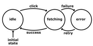
A state machine is a design pattern in computer programs or digital logic. This concept is used to simplify problems in a manageable way. There are two types of state machines: finite and infinite-state machines. The former is comprised of a finite number of states, transitions, and actions that can be modeled with flow graphs, where the path of logic can be detected when conditions are met.
A state machine is a programming architecture that allows dynamic flow to states depending on values from previous states or user inputs. State Machines are used in applications where distinguishable states exist.
We shall describe the design of the state machine by using our fictitious home automation system. When the owner of the house enters the house area then there is a gate in the yard. He needs to open it either by showing a mobile phone or by using a remote control. We shall build a model of the main gate of the yard. The gate can be in different states. These can be “CLOSED”, “OPENED”, “CLOSING”, “OPENING” and “BLOCKED” states. The default state is the “CLOSED” state. While the gate is opening then an obstacle (for example the dog of the house) can come in front of the yard gate. The gate must stop and stay in the same position. When the obstacle is removed the gate should continue opening or closing.
Down the sample project (HistoricalData_Hemelix.zip)
In most cases, we shall have a functional specification that describes how the system should work. The “OPENED/CLOSED” state is identified by using proximity sensors. When power is applied to the system, the gate can be in a partially open situation. We don’t consider it as a state since we have “OPENING/CLOSING” states. If the gate is in a partially open situation, we should close the gate. The system may not be able to close the gate due to obstacles that prevent it to close it. We have a through-beam sensor that checks the line of sight. If the sensor can’t see the other side it indicates there is an obstacle in the system. One important point to note is that system can go to the “OPENING” state directly from the “CLOSING” state. This can happen when the through-beam sensor can’t see the other side, in this case, it will “OPENING” state.
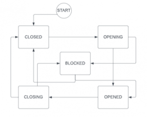
Figure 01: State Diagram of the Yard Gate sample (Yard gate moves from one state to another state)
We shall develop a state machine in the PLC program in Structure text programming language. This can be executed in any structured text-compatible PLC.
We can see from the state diagram, the gate should go to CLOSED state first. From CLOSED state it can directly go to OPENING state and then to OPENED state. If there is an obstacle then it goes to BLOCKED state and then to OPENED state. We need to declare a few enums for this purpose. Enum is a handy way to express something with text. We can define for example CLOSED state by number 1. But it is more expressive to write as CLOSED than 1.
The sample, we shall develop in this tutorial is our fictitious yard gate as shown in the following picture. When we press on the Open button the PLC program will activate the openOutput signal. When the door reaches the end, it will be indicated by OpenSwitch. If there is an obstacle then the gate should stop. When the obstacle is removed, it should continue opening or closing.
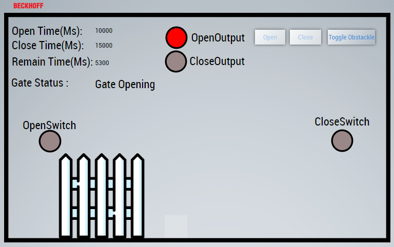
Figure 02: Visualization of the Yard Gate movement
How to insert enum:
=> Select DUT | ADD | DUT
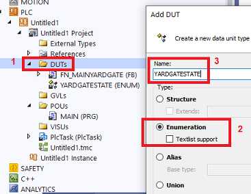
Figure 03: How to insert enum to solutions
Enum used in our yard gate:
TYPE YARDGATESTATE :
(
	YARD_UNINIT := 0,
	YARD_INIT,
	YARD_CLOSED,
	YARD_OPENING,
	YARD_OPENED ,
	YARD_CLOSING,
	YARD_BLOCKED
);
END_TYPE
Each state is described by an enum. Some people describe the states by a number. For example, YARD_CLOSED can be expressed by 50. But this may not be expressive. The above enums will describe the state of the Gate at a particular time. First, the state will be uninitialized, and then the initialization phase. The initialization phase depends on what kind of actuators. The actuators can be compressed air systems, hydraulic power, or direct AC/DC motor. In this gate project, we are using a direct DC motor.
If we express by number, it can be like the following but not so much expressive as compared to the code in the handling state section.
CASE state OF
10:
.........
20 :
.........
50 :
.........
END_CASE
Now, let’s create a skeleton state machine with the above enums. We declare a variable state of type YARDGATESTATE and initialize it to YARD_UNINIT. We use a case (switch in other programming languages).
state     : YARDGATESTATE := YARD_UNINIT;
stateInit : BOOL := FALSE;
With this initialization, in each PLC cycle, the code will check that the state is YARD_UNINIT and execute the statements under this case. If it finds any logic to jump to another state it will do, but in our skeleton, there is no way to go to other states. We need to change the code for that. If you have noticed, we have another variable called stateInit which is initialized to FALSE. When the state changes then we set this variable to FALSE. This will give a chance to execute state-specific code. In each state, we set the variable to TRUE for avoiding multiple time execution.
CASE state OF
    YARD_UNINIT:
    IF NOT stateInit THEN
        stateInit := TRUE;
    END_IF
    YARD_INIT  :
    IF NOT stateInit THEN
        stateInit := TRUE;
    END_IF
    YARD_CLOSED:
    IF NOT stateInit THEN
        stateInit := TRUE;
    END_IF
    YARD_OPENING :
    IF NOT stateInit THEN
        stateInit := TRUE;
    END_IF
    YARD_OPENED :
    IF NOT stateInit THEN
        stateInit := TRUE;
    END_IF
    YARD_CLOSING:
    IF NOT stateInit THEN
        stateInit := TRUE;
    END_IF
    YARD_BLOCKED :
    IF NOT stateInit THEN
        stateInit:= TRUE;
    END_IF
END_CASE
In the above code, there is no way to jump to other states. It will be all the time in the same state according to initialization. Here will show how we jump to other states.
YARD_UNINIT:
    IF NOT stateInit THEN
	stateInit := TRUE;
    END_IF
	state :=YARD_INIT;
	stateInit := FALSE;

YARD_INIT  :
    IF NOT stateInit THEN
	stateInit := TRUE;
	stateTimer(IN:=FALSE);
    END_IF
	stateTimer(IN:=TRUE, PT:= initTime);
    IF stateTimer.Q THEN
	state :=YARD_CLOSED;
	stateInit := FALSE;
    END_IF
...
When we declared the state variable, we initialized it to YARD_UNINIT. In this case, we are changing the state to YARD_INIT directly which means, in the next PLC cycle the state will be YARD_INIT.
Now in the YARD_INIT state, we initialize a timer (just to simulate, in a real system we might get some sensor input or wait for another device status). When the timer expires the state takes a new value (in this case YARD_CLOSED) and we set stateInit to FALSE.
Use a function block (FN_MAINYARDGATE) :
A function block is a POU, which returns one or several values when executed. The values of the output variables and the internal variables are retained until the next execution. This means that the function block may not return the same output values, if it is called repeatedly with the same input variables.
In the PLC project tree, function block POUs have the suffix (FB). The editor of a function block consists of the declaration part and the implementation part.
A function block is always called via an instance, which is a copy of the function block.
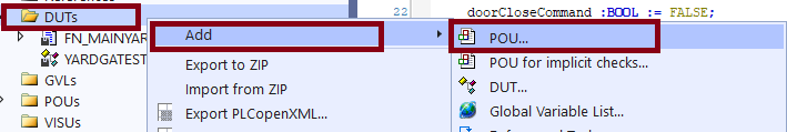
Figure 04: How to add function block
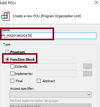
Figure 05: Naming and Selecting function block option
Calling a function block:
PROGRAM MAIN
VAR
     fnYardDoor : FN_MAINYARDGATE;
     isClosed : BOOL;
END_VAR
//Body
fnYardDoor();
isClosed := fnYardDoor.isClosed;
Variables for our function block :
We have few variables which we have declared to handle different states. Please read the comment of each variables to understand it’s purposes.
FUNCTION_BLOCK FN_MAINYARDGATE
VAR_INPUT
END_VAR
VAR_OUTPUT
	isClosed : BOOL;
END_VAR
VAR
//State variables
    state 	     : YARDGATESTATE := YARD_UNINIT ;
    lastMovement     : YARDGATESTATE := YARD_UNINIT ;
    stateInit : BOOL := FALSE;

//HMI variables
    stateDescription: STRING(255);
    remainingTime   : INT := 0;
    closingTimeLeft : INT := 0;
    openingTimeLeft : INT := 0;
    openTimeMs      : INT;
    closeTimeMs     : INT;
    gateOpenCommand :BOOL := FALSE;
    gateCloseCommand :BOOL := FALSE;

//Time and Timer
    initTime 			: TIME 	:= T#5S;
    openTime 			: TIME 	:= T#10S;
    closeTime 			: TIME 	:= T#15S;
    stateTimer 			: TON;
//Inputs outputs
    gateCloseProximitySensor : BOOL := TRUE;
    gateOpenProximitySensor : BOOL := FALSE;
    gateOpeningOutput : BOOL := FALSE;
    gateClosingOutput : BOOL := FALSE;
    movingObjectDetected : BOOL := FALSE;
END_VAR
Handling state:
A finite state machine is an abstract machine that can be in exactly one of a finite number of states at any given time. The finite state machine can change from one state to another based on some conditions, that change is called transition, and those conditions are called transition conditions.
We can describe a state by a number or by an enum. Enum is better in this sense it can be descriptive. For example, when the yard gate is closed we can express by a number 10 or by an enum YARD_CLOSED (for example). The state is described by the enum. Whenever we change state we might need to do some housekeeping tasks, for that purpose, we have a variable stateInit (BOOL type). Whenever we have assigned a new state then we set stateInit to false and when the initialization is done then we set stateInit to FALSE.
In our FN_MAINYARDGATE function block, we have a variable state which is initialized as
state : YARDGATESTATE := YARD_UNINIT ;
When the PLC cycle finds the state it will continuously execute this case. If we don’t set the state other than YARD_UNINIT then it will come to this case again and again. We are setting the stateInit to TRUE so single execution code area will be executed single time, but the multiple execution code are will be executed again and again until we set the state other than YARD_UNINIT. If we set the state to something else as shown in the next image, it will go to that state.
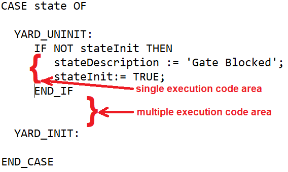
Figure 06: single execution code are and multiple execution code are
In figure 6, there is no code in the multiple execution area, so it means in each PLC cycle, nothing will be executed. If we take a look at figure 7, we are setting the stateTimer to TRUE with time initTime. For each PLC cycle, the input of stateTimer will be set to TRUE. When the time has elapsed (output Q is TRUE) then we set
state :=YARD_CLOSED;
stateInit := FALSE;
In the next PLC cycle, the state will be YARD_CLOSED, so it will execute the YARD_CLOSED case and shift from the YARD_INIT case.
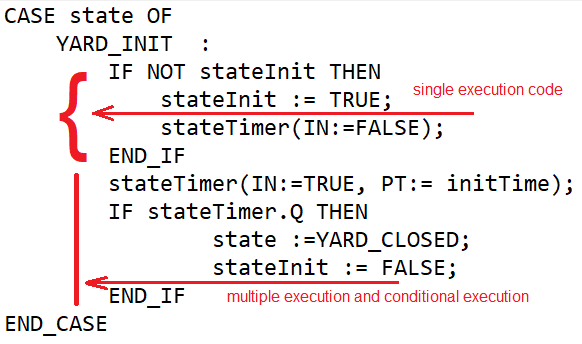
Figure 07: A way to skip multiple code areas by timer and setting new state value
processYardGate(); //Check if the open/close command is coming from HMI
CASE state OF
YARD_UNINIT:
IF NOT stateInit THEN  //it is new state, so we handle it
stateDescription := 'Gate Uninitialized';
stateInit := TRUE; //We indicate the state has been handled
END_IF
state :=YARD_INIT; // New state
stateInit := FALSE; //When new state case, we need to handle it again.
.........
YARD_BLOCKED :
IF NOT stateInit THEN
stateDescription := 'Gate Blocked';
stateTimer(IN:=FALSE);
doorCloseProximitySensor := FALSE;
doorOpenProximitySensor := FALSE;
doorOpeningOutput := FALSE;
doorClosingOutput := FALSE;
doorOpenCommand := FALSE;
doorCloseCommand := FALSE;
stateInit:= TRUE;
END_IF
stateTimer(IN:=TRUE, PT:= openTime);
IF NOT movingObjectDetected AND  lastMovement = YARD_OPENING THEN
state :=YARD_OPENING; //obstacle removed, continue
stateInit:= FALSE;
END_IF
IF NOT movingObjectDetected AND  lastMovement = YARD_CLOSING THEN
state :=YARD_CLOSING;
stateInit:= FALSE;
END_IF
END_CASE
Download the code and watch the YouTube Video.
This YouTube video has the following tutorial.
-Yard gate state machine implementation in structured text, PLC program (this one)
-HMI animation (https://www.hemelix.com/scada-hmi/twincat-hmi/animation-in-twincat-hmi/)
-Data historian (https://www.hemelix.com/scada-hmi/twincat-hmi/twincat-hmi-historize-symbol/)
Function Block Action and Method
Action :
An action does not have its own declarations and uses the data of the basic implementation. This means that the action uses the input/output and local variables of the basic implementation.
Creating an object Action
1. Select a function block or a program in the Solution Explorer in the PLC project tree.
2. In the context menu select the command Add > Action…
The dialog Add Action opens.
3. Enter a name and select an implementation language.
4. Click on Open.
The object is added to the PLC project tree and opens in the editor. In the following snippet, we are calling the action processYardGate() action.
...
processYardGate();
CASE state OF
...
Method :
A method contains a sequence of statements. In contrast to a function, it is not an independent POU, but has to be assigned to a function block or a program. You can use interfaces to organize methods.
Watch YouTube video
State machine design in ST
Data historian
Handling HMI request :
We need to listen when we have a request from HMI.
=>We add an action to our FN_MAINYARDGATE function block and call the action in each cycle
processYardDoor();
We have the following content of our action.
IF state= YARD_CLOSED AND doorCloseProximitySensor=TRUE AND doorOpenCommand= TRUE AND NOT movingObjectDetected THEN
state :=YARD_OPENING;
stateInit := FALSE;
END_IF
IF state= YARD_OPENED AND doorOpenProximitySensor=TRUE AND doorCloseCommand= TRUE AND NOT movingObjectDetected THEN
state :=YARD_CLOSING;
stateInit := FALSE;
END_IF
References:
=> https://www.hemelix.com/automation/structured-text-st-timer-in-details/
=> https://www.hemelix.com/scada-hmi/twincat-hmi/animation-in-twincat-hmi/
=> https://www.linkedin.com/pulse/efficient-plc-programming-using-finite-state-machine-concept-terzija/
=> https://stefanhenneken.net/2018/11/17/iec-61131-3-the-state-pattern/
=> https://www.plctalk.net/threads/state-machines-in-st-siemens-scl.54475/ (state handle)
Download the sample from the link given above.
See next, array in Structured Text https://www.hemelix.com/plc/array-and-enumeration-in-structured-text/
Ask questions related to Hemelix sample code and design at Google group https://groups.google.com/g/hemelix