
Installation and the first example
It is better to use the same version of the software as mentioned by Beckhoff to avoid complications as we have used in HMI development. It does not mean you have to use the same version as we have used here. For example, we can use all the latest versions from Beckhoff.
Download the sample application
=>We have used Windows 10 and Windows 7 for testing and developing the TwinCAT software
=> .Net 4.7.2 developer pack or equivalent (https://dotnet.microsoft.com/download/dotnet-framework/net472)
=> Visual Studio (2013, 2017 or 2019) community (make sure to include web-related components if visible) or pro version https://visualstudio.microsoft.com/downloads/
=> TwinCAT 3.1 – eXtended Automation Engineering (XAE), version 3.1.4024.7 (https://beckhoff.com/)
=> TE2000 | TC3 HMI , version 1.10.1336.404 (https://beckhoff.com/ for developing HMI and GUI)
Beckhoff software has an engineering version and run time version. We shall use the engineering version for developing the application and on the other hand, run time is used for only executing the program. One good example is that when we install Beckhoff TwinCat Software to PLC, we install only the run time version. Even it is not possible to install the engineering version to PLC due to memory constraints. The engineering version offers all the development, debug, etc tools on top of run time.
Download all the software and run those executables as administrator. Good to install visual studio before installing TwinCAT 3.1
Now we should have all the necessary software so we can start to develop.
=>Start Visual Studio
=>Select TwinCAT PLC template as shown in the following figure.
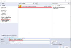
Figure 01: Template selection in visual studio
Visual studio will create a solution as shown in the following figure
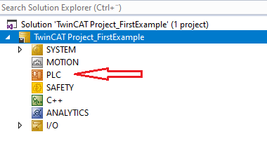
Figure 02: PLC project selection
=>Select PLC as shown in the above image then press on right mouse, then add new item, standard PLC project and finally press Add to complete.
Now we should have something like the following image.
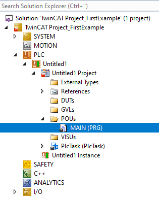
Figure 03: Inserting MAIN project (Program entry point)
Now double click on the MAIN (PRG) and it will open an editor where we can replace it with the following code (by copy paste to the upper part and lower part of the editor).
//Header, upper part
PROGRAM MAIN
VAR
testBool : BOOL := FALSE; //This variable is used for Boolean variable
testInt : INT := 0;
testReal : REAL := 3.14;
(*  Multiple line comment
*)
testString : STRING := 'MyString';
myTimer : TON;
END_VAR
//Lower part (body of the program)
myTimer(IN:= TRUE, PT:=T#500MS);
IF myTimer.Q = TRUE THEN
myTimer(IN:= FALSE);
testInt := testInt +1;
IF testInt > 30999 THEN
	testInt:= 0;
END_IF
END_IF
Description of the program:
The upper part of the page is the header where we declare variables ( we call it also tag or symbol in PLC world). This is just a convenient way of accessing the content of the PLC. A good naming convention can be helpful for better readability and maintenance.
We have declared a boolean (for holding true or false value) variable as testBool. It has been initialized as false. See the difference between how we declare this variable in different languages.
testBool : BOOL := FALSE; // in structured text language
Boolean testBool = false; // in C#, Java etc programming language
In the same way, we have declared other few variables testInt (integer type, initialized to 0), testReal (real number, initialized to 3.14), testString (a string type, initialized as “MyString”). All these are declared inside VAR and END_VAR block.
Comment in ST:
Comment | Description | Sample: |
|---|---|---|
Single line | Starts with // and ends at the end of the line. | //my single line comment, this will be ignored |
Multi-line | Starts with (* and ends with *). | (* Multiple line comment, we can have many lines *) |
Nested | Starts with (* and ends with *). Additional (*…. *) comments can be contained within this comment. | (*a:=34;(*1.a comment*)b:=b+1;(*2.another comment*)*) |
We have used a timer variable as well. The timer will give a signal every 500 milliseconds then we increase the integer type variable (testInt) by one just to show that the program is doing something. Since the testInt is a signed number, we reset it when it reaches 30999. See different data types used in PLC structured text (https://www.hemelix.com/automation/data-type-used-in-plc-programming/)
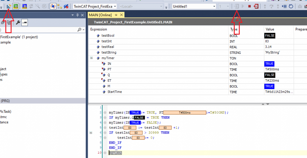
Figure 04: Sample project running in Visual Studio
If we activate the program by pressing activate button in visual studio (arrow 1) and then log in to the program (arrow 2) we see the above program running.
Some additional information related to the Visual Studio menu is shown in the image below.
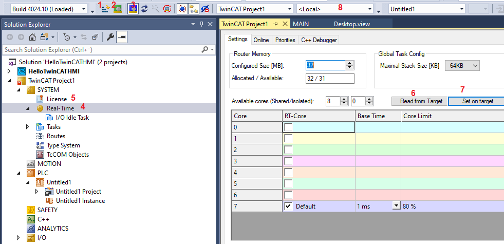
Figure 05: License settings for the project
1 => Activate the program (including download to the target either PLC hardware or simulator) after these programs are executed.
2 =>Target is switched to run mode, in this mode programs are executed (config mode allows to configure, scan hard wares which are connected to the PLC by different bus).
3 =>Target is switched to config mode, in this mode programs are not executed and it allows configuration of the program, such as scanning I/O cards, etc.
4 => Configure the core of the PLC or PC where we target to run,
5 => Allow to insert license for the TwinCAT Software, we can activate 7 days license freely.
5a =>You might need to activate the project and running if you want to be sure that the license has been effective!
6 => Read the number of cores in the PLC or simulator (if running in the development computer)
7 => Set the core in the PLC or simulator (if running in the development computer) where the program will be executed
8 => It allows us to select where we should run the program to a simulator (local PC, IP address is 127.0.0.1)
Congratulations! you have made your first ST program that is running in TwinCAT simulator.
Explanation of the program:
This is a very simple program, we are declaring 4 variables (those types are BOOL, INT, REAL, and STRING), and those variables are initialized with some default value. We have also declared a timer that ticks on each 500MS interval. testInt variable is increased by one on each timer tick, when the variable value is higher than 3099 then we reset the variable to 0 and it continues with this cycle until we stop the program.
Operator in Structured text:
Operation | Symbol | Binding strength |
|---|---|---|
Put in parentheses | (expression) | Strongest binding |
Function call | Function name (parameter list) |
|
Exponentiation | EXPT |
|
Negate | – |
|
Multiply | * |
|
Add | + |
|
Compare | <,>,<=,>= |
|
Equal to | = |
|
Boolean AND | AND |
|
Boolean XOR | XOR |
|
Boolean OR | OR | Weakest binding |
Modulo Operator
Modulo (MOD) is special type of operation. For example, (myVar MOD 10) will produce the reminder as result. If the value of myVar is 11 then (myVar MOD 10) will produce 1, if myVar is equal to 10 then (myVar MOD 10) will produce 0.
Following is an example, when the reminder is equal to 5 then we do something.
VAR
columnVal  : INT ;
myVar  : INT := 54;
END_VAR


//If reminder is 4 then we set columnVal  to 30
IF ( ( myVar MOD 10 ) = 4 ) THEN
	columnVal := 30;
END_IF
Some Useful Icons in VS Tool
Sometimes we need to reset the program. In the following diagram, it shows the major functionalities.
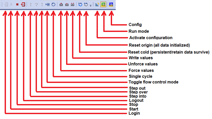
Figure 06: PLC program related features in Visual Studio toolbox
See also:
Tips:
=> If you run the test sample on your PC then the PLC and PC should be in the same network (same LAN or VPN)
=> The PLC AMS Net ID should be added to the PC, more https://www.hemelix.com/automation/structured-text-how-to-add-route-for-plc/
=> Comment, make sure there is space (*my comment*) <= invalid (* my comment *) <= Valid because of space
Download the sample from the link given above.
Next, let’s try to understand user control at https://www.hemelix.com/plc/structured-text-st-timer-in-details/
Ask questions related to Hemelix sample code and design at Google group https://groups.google.com/g/hemelix