Usages of IO cards (under update)
EtherCAT Couplers
The EtherCAT Couplers are the link between the EtherCAT protocol at fieldbus level and the EtherCAT Terminals. Since communication in the EtherCAT system is continuous through to the last terminal, the coupler only converts the physical layer without changing the process data stream.
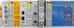
The EK1100 EtherCAT Coupler is the link between the EtherCAT protocol at the fieldbus level and the EtherCAT Terminals. The coupler converts the passing telegrams from Ethernet 100BASE-TX to E-bus signal representation. A station consists of a coupler and any number of EtherCAT Terminals that are automatically detected and individually displayed in the process image. The following image shows 2 sensors are connected to a terminal (EL3702) along with EK1100 coupler (from Beckhoff.com). There are many different types of couplers, some work with RJ45 connection, and some work with fiber optics. EK1100 works with RJ45 connection. The coupler can be connected directly to PLC or to a switch depending on our needs.
Figure 01: EtherCAT coupler with 2 RJ45 port + 2 Sensor connected to EL3702 terminal card
The following figure shows how a coupler can be connected to Beckhoff PLC (CX2040). From a coupler, we can connect to another coupler, and so on. On the other hand, we can have a switch CU2508 and we can connect PLC to the switch and more than one couplers can be connected to the switch.
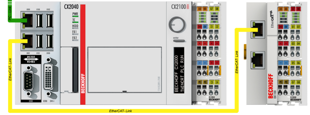
Figure 02: EtherCAT coupler with PLC (CX2040)
Reading Boolean Variables
Boolean variables are either true or false. For example, a motor is running or not. The machine is ON or OFF. We read those variables from the process level by the EtherCAT Terminals EL1xxx, ES1xxx, and ELX1xxx series. This signal is transmitted via EtherCAT to the higher-level automation device for further processing. See a practical example, https://www.hemelix.com/scada-hmi/twincat-hmi/hmi_ecdiagnosticscontrol/ (see figure 2). If the sensor (which provides the ON or OFF data) needs power it can be supplied by the +24V channel. The signal is connected to the input channel. When the signal is HIGH then the voltage in the channel will be HIGH. We can measure the voltage when HIGH and low by voltmeter.
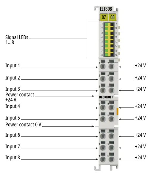
Figure 03: EtherCAT terminal EL1808 (I/O card for reading input signal)
Normally the card is identified by yellow color. Also IO link variables in Visual Studio have similar color so we can trace easily which type of cards it is.
Writting Boolean Variables
Writing Boolean variables
Reading Analog Data
An analog signal is time-varying and generally bound to a range (e.g. +4 mA to +20 mA), but there is an infinite number of values within that continuous range. An analog signal uses a given property of the medium to convey the signal’s information, such as electricity moving through a wire. In an electrical signal, the voltage, current, or frequency of the signal may be varied to represent the information. Analog signals are often calculated responses to changes in light, sound, temperature, position, pressure, or other physical phenomena.
Compared to digital binary data, for example, a motor is running, TRUE or FALSE, there can’t be anything between these two values but for current measurement, there could be a range of values between 4 mA to 20 mA
See digital analog converter at https://www.monolithicpower.com/en/analog-vs-digital-signal
Writting Analog Data
Reading Serial Data
Writting Analog Data
Wring Analog variables
Readin Serial Data
Wring Serial Data
Power Supply Terminals
Power Supply to Cards