The actual content is coming soon. We shall develop a software that will control our home automation projects and devices with Raspberry pi.
Tips:
01. makefile:4: *** missing separator. Stop
=> Solution, convert space to tab in the makefile (use Notepad ++, Edit | Blank Operation | Space to Tab)
02. Updating Pi
=> sudo apt dist-upgrade
03. Installing Wiringpi
=> cd /tmp
wget https://github.com/WiringPi/WiringPi/releases/download/2.61-1/wiringpi-2.61-1-armhf.deb
sudo dpkg -i wiringpi-2.61-1-armhf.deb
# Test
sudo gpio -g mode 19 out
sudo gpio -g write 19 1
04. Update Tool Chain
=> sudo apt update
sudo apt dist-upgrade
sudo apt-get install build-essential gawk gcc g++ gfortran git texinfo bison libncurses-dev
05. How to compile from commandline
=> gcc -o led_blink led_blink.c -l wiringPi
06. Download Source code
=> git clone https://github.com/WiringPi/WiringPi.git, go to the folder and ./build
07. Libmodbus Installation
=> sudo apt install libmodbus-dev
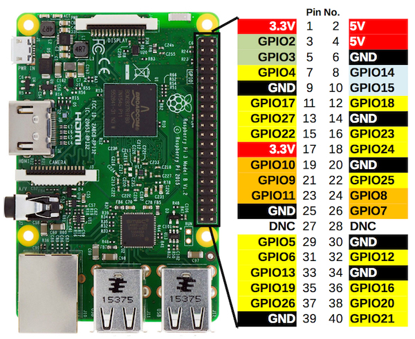
08. Physical PINs (Image source https://toptechboy.com/understanding-raspberry-pi-4-gpio-pinouts/pinout-corrected-2/)
Download and launch the Raspberry Pi Imager
=> https://projects.raspberrypi.org/en/projects/raspberry-pi-setting-up/2
L298N motor Driver
L298N is a motor driver, which can be used to control a DC motor. We shall use this module to control motor over Modbus TCP.
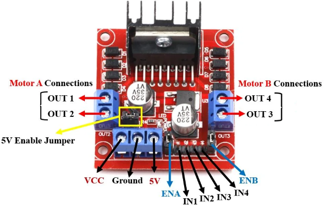
Jumper: jumper in place – uses the motors power supply to power up the chip. Jumper removed: you need to provide 5V to the +5V terminal. If you supply more than 12V, you should remove the jumper
VCC : This is the pin which supplies power to the motor. It can be 6-12V.
Ground : This is the common ground pin.
5V: This pin supplies the power (5V) for the internal circuit (L298N IC).
ENA: This pin controls the speed of the motor A by enabling the PWM signal (connect to lower pin of ENA).
IN1 & IN2: These are the input pins for motor A. They control the spinning direction of motor A.
IN3 & IN4: These are the input pins for motor B. They control the spinning direction of motor B.
ENB: This pin controls the speed of the motor B by enabling the PWM signal.
OUT1 & OUT2: OUT1: Positive terminal, OUT2: Negative terminal
OUT3 & OUT4: OUT3: Positive terminal OUT4: Negative terminal
Connect Pi to Laptop:
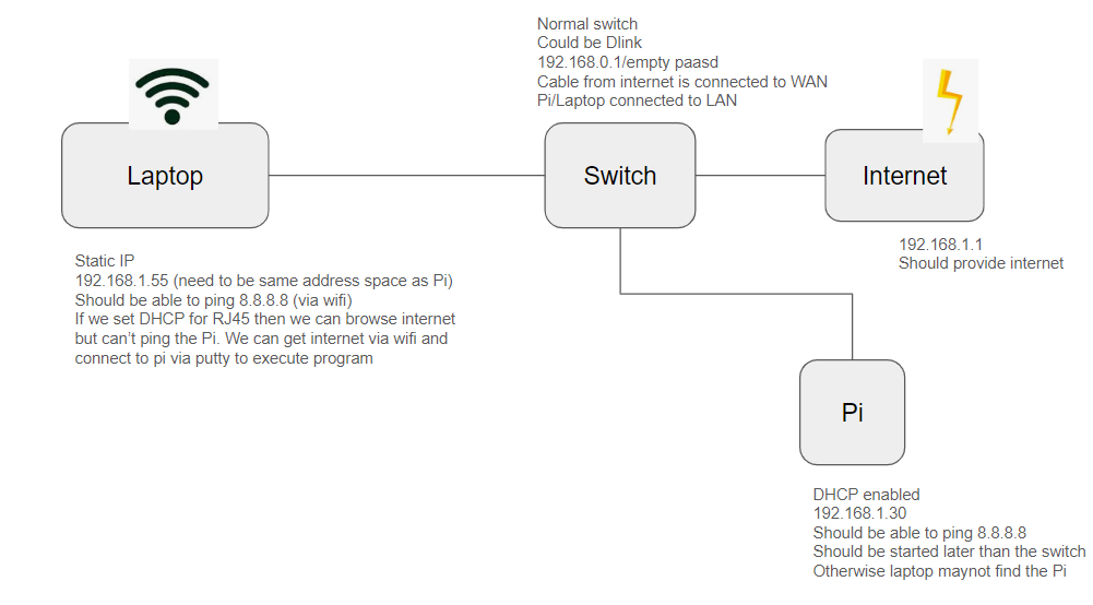
If we have above set up we can have internet in the laptop and we can compile and execute program in the pi. If we have enabled VNC remote desktop we can directly access the pi without any display, mouse and keyboard.
References:
=> Remote Desktop connection from Windows to Pi
=> https://microcontrollerslab.com/dc-motor-l298n-driver-raspberry-pi-pico-tutorial/
=> https://www.cs.colby.edu/maxwell/courses/tutorials/maketutor/ (Create make file)
=> https://www.electronicwings.com/raspberry-pi/raspberry-pi-gpio-access (GPIO and BCM)
=> https://www.raspberrypi-spy.co.uk/2012/06/simple-guide-to-the-rpi-gpio-header-and-pins/
=> https://www.linux4sam.org/bin/view/Linux4SAM/AT91Bootstrap
=> http://siliconkit.com/mirror/corewind/www.at91sam.org/note/note252.html
=> https://www.raspberrypi.org/
=> https://pimylifeup.com/raspberry-pi-python/
=> https://www.linux-magazine.com/Issues/2022/258/OPC-Unified-Architecture
=> https://www.maketecheasier.com/control-led-brightness-raspberry-pi/
=> https://www.google.com/search?q=OPC+server+to+raspberry+pi&rlz=1C1DIMC_enFI890FI890&oq=OPC+server+to+raspberry+pi&gs_lcrp=EgZjaHJvbWUyBggAEEUYOTIICAEQABgWGB4yCAgCEAAYFhgeMggIAxAAGBYYHjIICAQQABgWGB4yCAgFEAAYFhgeMggIBhAAGBYYHjIICAcQABgWGB4yCAgIEAAYFhge0gEIODc0MmowajeoAgCwAgA&sourceid=chrome&ie=UTF-8