Modbus Protocol
The Modbus protocol exchanges information using a request-reply mechanism between a master (client) and a slave (server). The master-slave principle is a model for a communication protocol in which one device (the master) controls one or more other devices (the slaves). In a standard Modbus network, there is 1 master and up to 31 slaves.
Important rule about Modbus:
The master-slave principle is characterized as follows:
Only 1 master is connected to the network at a time.
Only the master can initiate communication and send requests to the slaves.
The master can address each slave individually using its specific address or all slaves simultaneously using address 0.
The slaves can only send replies to the master.
The slaves cannot initiate communication, either to the master or to other slaves.
Several versions of Modbus have been developed to suit the transmission medium being used.
Most common are:
Modbus RTU (Remote Terminal Unit) – typically for use over RS-232 single-ended or RS-485 differential lines, uses binary coding and CRC error checking.
Modbus ASCII – also for use over RS-232 or RS-485 lines, uses ASCII characters instead of binary, making it more readable but less efficient, and it uses less effective LRC error checking. ASCII mode uses ASCII characters to begin and end messages whereas RTU uses time gaps of 3.5 character times for framing. Modbus ASCII messages require twice as many bytes to transmit the same content as a Modbus RTU message.
Modbus TCP – for use over TCP/IP networks, typically Ethernet communication is used for this.
The following figure shows how the client (master) can initiate a request to the server for some information. The client asks for the information by using the message format and the server responds to the message.
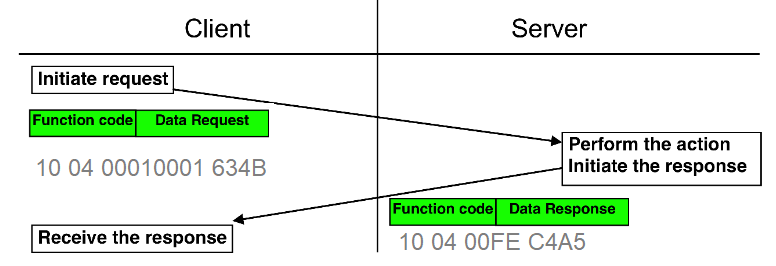
Figure 01: Message passing between client (master) and server (slave)
In the above figure we have some hexadecimal data for client and server, here are the translations of those data (see also the message format in the following figure ).
Request:
10 = Slave ID
04 = Function code (Reading input registers)
00010001 = Data to indicate to the server what to do
634B = CRC
Response:
10 = Slave ID
04 = Function code (Reading input registers)
00FE = Result of the request
C4A5 = CRC
Most used Function Codes
Read:
01: Coils (FC=01)
02: Discrete Inputs (FC=02)
03: Multiple Holding Registers (FC=03)
04: Input Registers (FC=04)
Write:
05: Single Coil (FC=05)
06: Single Holding Register (FC=06)
0F: Multiple Coils (FC=15)
10: Multiple Holding Registers (FC=16)
The following figure shows how the client (master) and slave (server) can be connected physically. Each slave has an ID. The master sends information with an ID to all slaves but only the target slave will respond to the master.
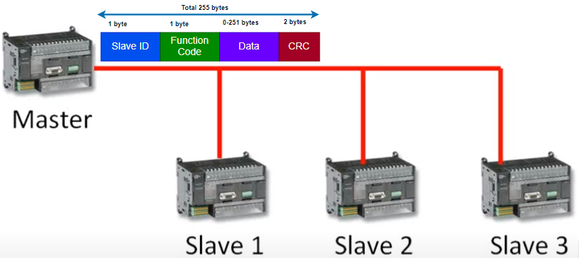
Figure 02: Physical connection between master and slave (For RTU we use ID and for TCP we use IP address)
We call sometime the client as master and server as slave. Modbus RTU works mainly with RS485 on the other hand Modbus TCP works on top of TCP/IP with IP address.
Modbus RTU
Protocol Data Unit (PDU) :
The Function Code that indicates the kind of action to be performed.
The Data Field of frames sent from a master to slave devices that contains additional information about action defined by the function code. This can include items like discrete and register addresses, the quantity of items to be handled, and the count of actual data bytes in the field.
Application Data Unit (ADU) contains:
The Protocol Data Unit (PDU)
The Slave ID, the unique address from 1 to maximum number of Slaves for each master.
The CRC Error Check
Error Codes – When the server responds to the client it uses the function code field to indicate either a normal (error-free) response or that some kind of error occurred, called an exception response. For a normal response the server simply echoes the original function code and returns the data requested.
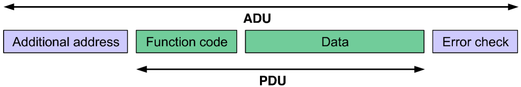
Figure 03: Protocol data for Modbus RTU
Following figure shows the main usages of Modbus protocol
Discrete Outputs or Coils: These are read/write registers/references that hold only a single bit each.
Discrete Inputs: These are read only registers/references and these too hold only a single bit each. Since they are read only, master devices can read data from these references but can’t change them.
Input Registers (Input Data): These are similar to Discrete Input in that these are read only but can hold up to 16 bits each.
Holding Registers (Output Data): These are similar to Discrete output in that these are read/write but can hold up to 16 bits each.
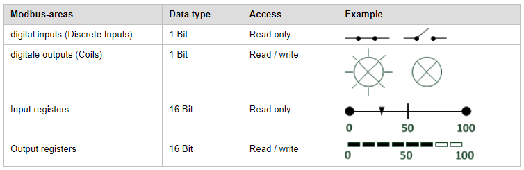
Figure 04: Data type and typical usages
Data type and access right for Master and slave are shown in the following figure.
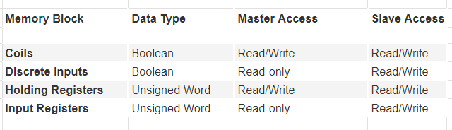
Figure 05: Data type, Master and Slave access right
Information is stored in the Slave device in four different tables: two for coils and two for registers. Each table has 9999 possible addresses. Coils are discrete values (1 bit each) and registers are numerical values (each 1 word = 16 bits = 2 bytes). The following table contains the basic Modbus data types defined by the specification.
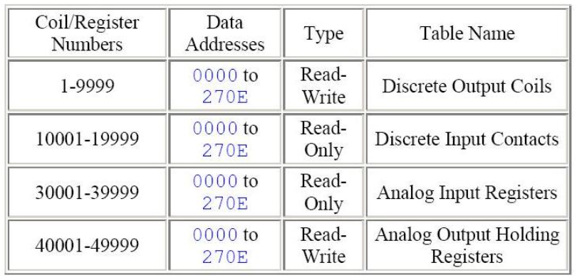
Figure 06: Data area for modbus protocol
Modbus TCP/IP
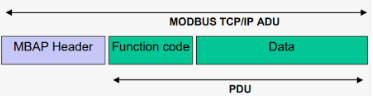
Compared with Modbus RTU protocol, Modbus TCP protocol adds an MBAP message header to RTU protocol, and since TCP is based on reliable connection service, the CRC check code in RTU protocol is no longer needed, so there is no CRC check code in Modbus TCP protocol.
TCP is a connection-based protocol so a connection must be established before transferring data.
Modbus TCP simply takes a Modbus RTU message, transmits it with a TCP/IP wrapper and sends it over network instead
of serial lines.
The packet is composed by six parts:
=> Transition ID: 2 bytes set by the client to uniquely identify each request
=> Protocol ID: 2 bytes set by the client, always 0000
=> Length: 2 bytes for number of bytes in the message to follow
=> Unit ID: 1 byte set by the client and echoed by the server
=> Function Code: the table to access and whether to read or write
=> Data
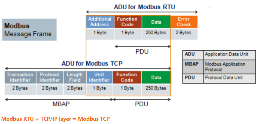
Figure 07: Data presentation for Modbus RTU and Modbus TCP (source: internet)
Modbus RTU, for instance, utilizes serial communication for data exchange between devices, making it ideal for systems that require simple, robust, and cost-effective communication. Modbus RTU is often used in applications such as building automation, industrial process control, and remote monitoring.
On the other hand, Modbus TCP leverages Ethernet and IP networks for communication, providing increased speed and scalability in more complex and demanding environments. Modbus TCP is commonly found in applications that require high-speed communication such as power generation, oil and gas, and data center management.
TwinCAT Modbus SW :
Checksum:
CRC can be computed by program in the following way:
// Compute the MODBUS RTU CRC
UInt16 ModRTU_CRC(byte[] buf, int len)
{
  UInt16 crc = 0xFFFF;

  for (int pos = 0; pos < len; pos++) {
    crc ^= (UInt16)buf[pos];          // XOR byte into least sig. byte of crc

    for (int i = 8; i != 0; i--) {    // Loop over each bit
      if ((crc & 0x0001) != 0) {      // If the LSB is set
        crc >>= 1;                    // Shift right and XOR 0xA001
        crc ^= 0xA001;
      }
      else                            // Else LSB is not set
        crc >>= 1;                    // Just shift right
    }
  }
  // Note, this number has low and high bytes swapped, so use it accordingly (or swap bytes)
  return crc;
}
Tips:
01: => Illegal data address
The illegal data address error occurs if the server rejects the combination of the starting register and length used. One possibility is a mistake in your program on the starting register number. For example, the master expects data of 20 bytes, and the server supplies more than 20 bytes. This typically can happen for example data has been changed at some point and we forget to modify the changes.
References:
=> https://pymodbustcp.readthedocs.io/en/latest/quickstart/index.html
=> https://stackoverflow.com/questions/29602698/create-a-simple-client-server-using-modbus-in-c
=> https://crccalc.com/ (Calculate Modbus Checksum online)
=> https://www.fernhillsoftware.com/help/drivers/modbus/modbus-protocol.html
=> https://www.modbustools.com/modbus.html
=> https://www.picotech.com/library/oscilloscopes/modbus-serial-protocol-decoding
=> https://www.hemelix.com/wp-content/uploads/2023/09/Modbus_Application_Protocol_V1_1b3.pdf