How do I remove my program which has been corrupted?
Symptoms:
In windows 9000 series, our program can be corrupted sometimes (may be program fault) and we can’t connect to the device by using visual studio.
If we use CeRHost to connect, we can connect but we find that the TwinCAT run mode is partially green.
Solution:
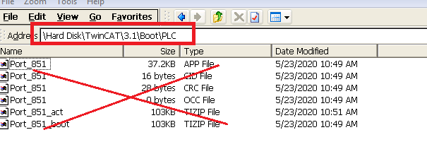
=> Press on Start then Run and in the Open edit box type Explorer and browse to \Hard Disk\TwinCAT\3.1\Boot\PLC
=> Remove all contents and restart the PLC
=> Now we should be able to connect from Visual Studio with our program and we see that TwinCAT is in run mode if we run our program
How do I add new I/O cards
Problem:
We have a program with variables linked. Now we can add new I/O cards before existing configured cards or after the existing configured cards. How to we keep the old linked variables?
Solution:
We shall consider 3 scenarios.
Inserting a new card after the original cards
Inserting a new card in the middle of existing cards
Inserting a new card before the original cards
A. Inserting a new card after the original cards
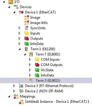
In this scenario, we have an I/O card already configured (variables are linked). We add a new card after the cards. When we add new card then the configuration should be updated in visual studio. At the same time, we need to keep the existing variables in linking state. We have only one card inserted Term 7 (EL6001) a serial data reader.
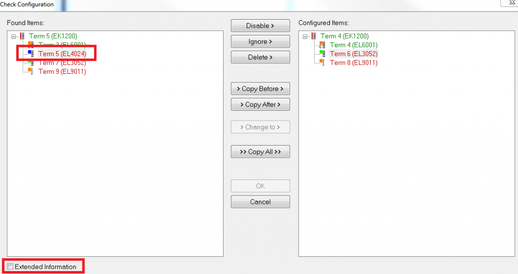
Now we shall add couple of cards after the existing cards and show how to keep the card 6001 (variable linked). We add 2 cards (EL4024 and EL3052) and scan again (The PLC should be in config mode).
Configured Items:
Those items are configured in the visual studio, meaning what we see under the Device (EtherCAT).
Found items:
Those items which are found by the recent scan. Mostly the IO cards are displayed according to the order it has been inserted in the stack.
We can the organise the items in visual studio as well. If we can drag and drop an items before and after by drag and drop. If we drop something on top of another item then the first item will go before another item.
For example, if we drop X on top of Y then Y will come before X. It will be seen in Visual Studio IO list and
Y
X
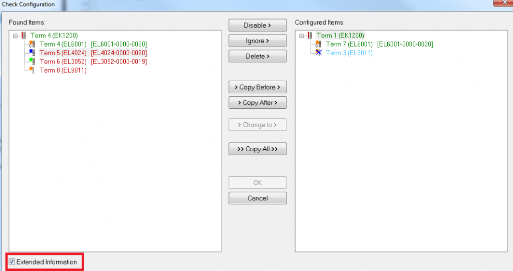
As we can see in the left box, scanning has found 2 new cards after EL6001. We can check Extended information marked to get more information.
Don’t use >> Copy All >> from left to right. This will remove the existing links
Select individual card and use >Copy Before> or >Copy After> to match the configured items
When we have matched information we can press OK to accept the changes.
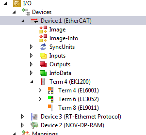
In this way, we can reuse the existing linked variables which we have done earlier time.
B. Inserting a new card in the middle of existing cards
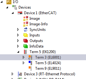
We have EL6001 and EL3052 cards in the current configuration. Now we shall add a new card in the middle of existing cards and show how to configure it. These 2 cards have linked variables.
We get the following dialog when we scan the bus again. New I/O card EL4024 is high lighted. Again >>Copy All>> will copy only the items (not the linked variables), so we shall loose it and that we don’t want.
Best option should be to use select EL3052 and >Copy Before> and then press OK
C. Inserting a new card before the original cards
In this configuration, we have an existing configuration and we add a new card in the first place. The original configuration is shown in the following image. We have configured EL6001 and EL4024 I/O cards.
Now we have added EL3052 card in the first place and scanned the bus. We got the following configuration dialog.
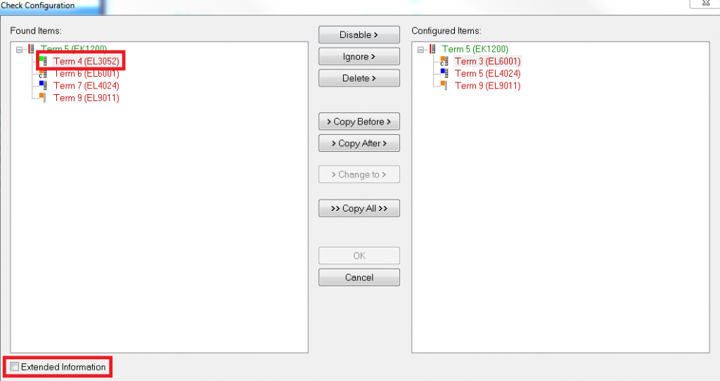
Now we select EL6001 from right side box and select >Copy Before>> and get the identical settings and press OK
Sync Unit Assignment (How to synchronized broken topology )
Line, tree or star: EtherCAT supports almost any topology. Sync Units define independent units of IO devices. Each unit contains process data that is consistent and synchronized. Sync Units can combine data from different slave devices. A process data diagnosis is performed cyclically for each Sync Unit.
Fieldbus devices can be grouped into Sync Units. If a field bus device fails within a Sync Unit, then devices of the own Sync Unit are marked as faulty, but devices in other Sync Units are not affected by this. Sync Units should be created if an EtherCAT slave device is expected to fail. For example, the supply voltage for a system section could be switched off for safety reasons. Sync Units must be created if fieldbus segments are to be switched off and other devices are not to be affected by this.
Sync Units help to structure applications. They are useful for applications in which machine parts can be switched off but the rest of the machine is to continue working.
How to create sync unit:
Open the “Sync Unit Assignment” dialog by selecting the corresponding EtherCAT master device in the I/O tree and clicking the “Sync Unit Assignment…” button on the “EtherCAT” tab.
https://infosys.beckhoff.com/english.php?content=../content/1033/tc3_io_intro/1468206859.html&id=6053821954081018594